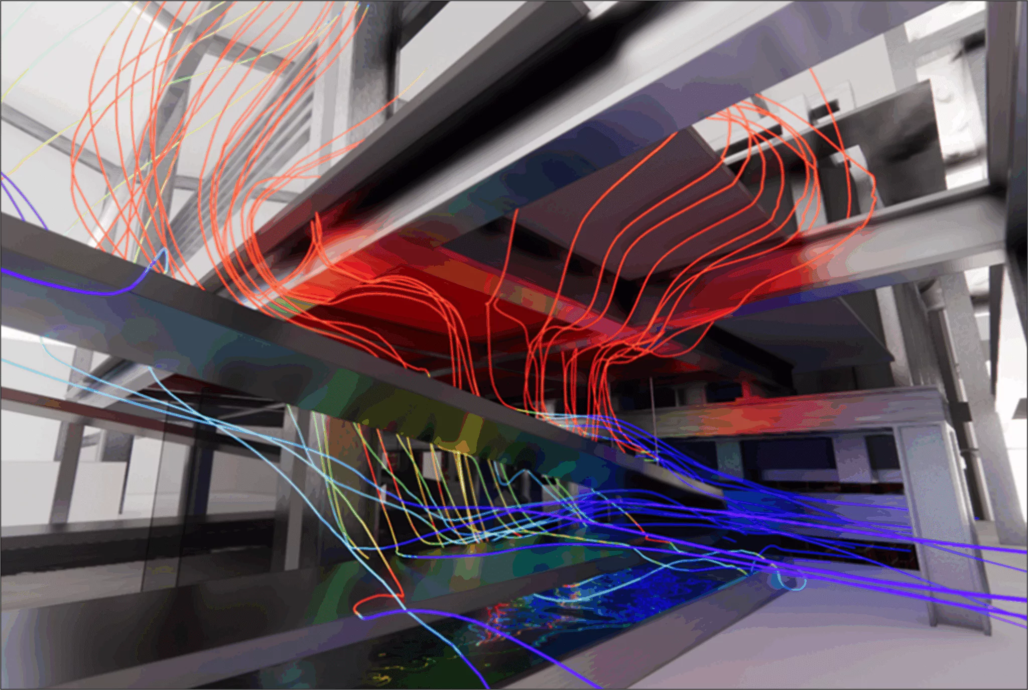
CFD thermo-airflow study of replacing a silica-melting furnace with an electric furnace: mapping the radiation on the structures, protection of the beams and thermal comfort of the operators.
EOLIOS's expertise in CFD simulation and in thermal analysis of structures played a decisive role in the study of an industrial furnace generating intense radiation on the steel beams, leading to deformation risks. Our know-how made it possible to map the structural temperatures and predict the overheating zones, while assessing the thermal comfort of the employees, to optimise the safety of the installations and ensure acceptable working conditions.
The essentials. To prepare the replacement of an oil-fired furnace with a more powerful electric furnace, EOLIOS ran a CFD thermo-airflow study of the silica-production hall. Two challenges: protect the steel beams from the radiation of the casting (up to 480 °C simulated without protection) and preserve operator comfort. Insulated U-shaped radiation shields, thermal curtains and a façade opening bring the beams below 100 °C and keep the work-zone air close to outdoor conditions.
On an industrial site dedicated to the manufacture of technical silicas, used in various sectors such as tyres or cosmetics, the process relies on the high-temperature melting of sodium silicate. Once brought to around 1200 °C, the molten material is directed to ingot moulds, where it is cooled by water spray before being temporarily stored in a pit.
As part of an energy transition, the site plans to replace an existing oil-fired furnace with a new-generation electric furnace, more efficient and less emissive. This technological change nevertheless brings new challenges, in particular linked to the increase in thermal power, the rise in radiated temperatures and the risks of structural heating in a partially open hall.
It is in this context that EOLIOS stepped in to carry out a complete thermo-airflow study. The objective: to assess precisely the thermal impact of the future furnace on its immediate environment, relying on advanced numerical modelling (CFD) and on an on-site audit of the existing conditions. The analysis covered two parts: a first phase dedicated to the current configuration of the installation, serving as a reference for comparison, and a second dedicated to the design of the project, integrating fine simulations of radiation and air circulation.
The study aimed to answer several challenges: guaranteeing the mechanical strength of the beams exposed to radiation, preserving the thermal comfort of the operators and anticipating any adjustment needs in terms of natural or mechanical ventilation. In an environment with high thermal inertia, optimising the airflow behaviour and passive protections becomes a strategic lever for performance and durability.
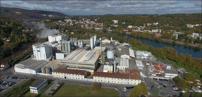
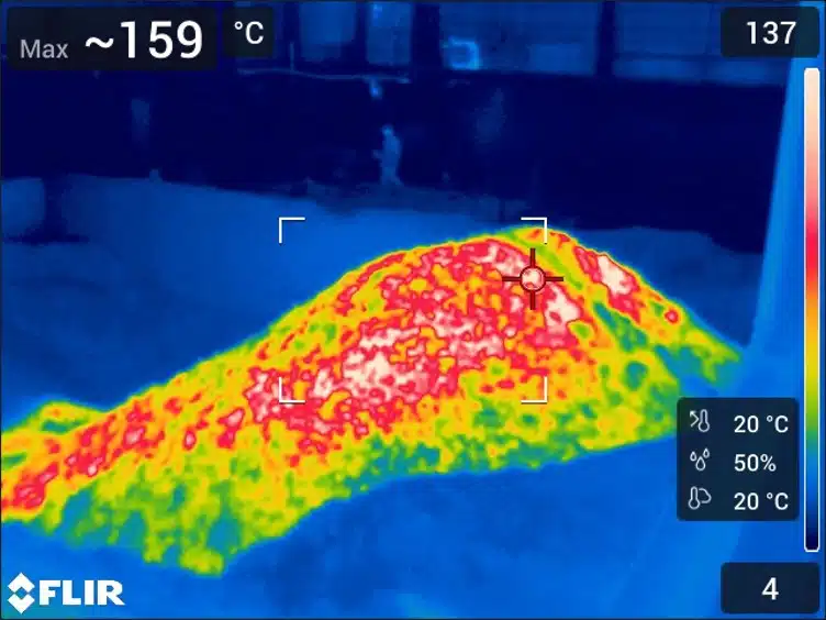
Replacing the oil-fired furnace with a higher-capacity electric furnace intensifies the thermal process, with melting temperatures still close to 1200 °C and a doubled flow rate. The main challenge identified concerns the thermal radiation generated by the molten glass, particularly at the outlet of the casting spouts. This radiation directly affects the load-bearing structures of the building, and in particular the steel beams located above the ingot moulds. These elements are designed for limit temperatures that can be locally exceeded, as shown by the thermographic surveys carried out during the initial audit. The risk is not only mechanical: it also concerns the durability of the materials, the strength of the fixings and the reliability of the equipment located nearby.
Thermal radiation is the transfer of heat by electromagnetic waves, without contact or intervening air. A very hot body like molten glass emits a flux that heats exposed surfaces at a distance, here the beams above the casting. A reflective radiation shield intercepts this flux.
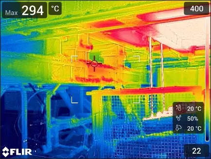
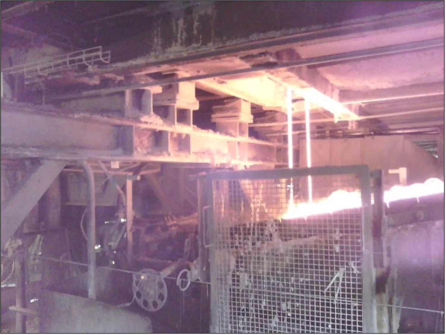
Alongside these radiation issues, the operation of the furnace generates a powerful upward air circulation, linked to the intense heat release in a building largely open to the outside. The dynamics of the airflows are complex: natural thermal draught, wind speed, building shapes, suspended platforms and mechanical obstacles interact to produce recirculation zones or heat stagnation in localised, often critical areas of operation. The simulations thus highlighted streams of hot air running along certain walls, residual heating in the pit or ventilation zones, and significant differences between the north and south of the hall.
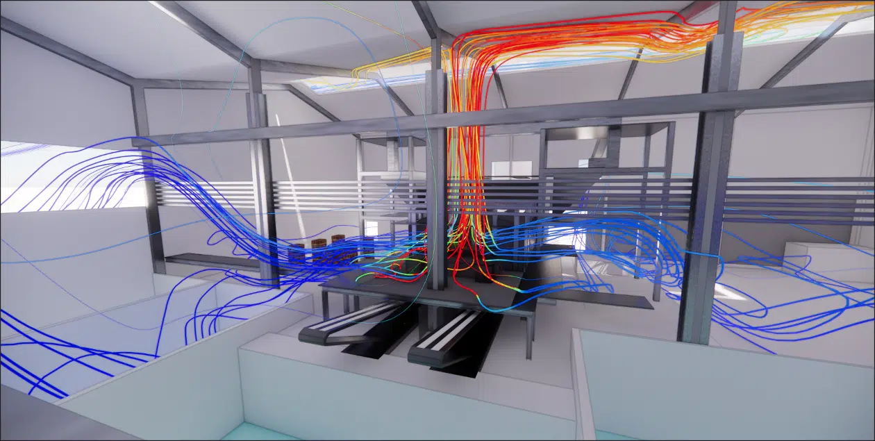
Finally, these phenomena directly impact the working conditions in the occupied spaces. The absence of an opening to the south, the addition of tarpaulins to limit the dust or the configuration of the pits can lead to localised overheating in certain sensitive zones of the building: casting platforms, circulation zones, mezzanines or technical rooms. Temperature differences of +10 to +15 °C compared to the outside were identified in some cases. This situation can generate thermal discomfort for the operators, or even constraints on the equipment, all the more so in the modelled summer conditions.
Before any modelling, an airflow and thermal audit mission was carried out on site by the EOLIOS engineers. This initial phase made it possible to collect precise data on the real operating conditions of the production hall. Thermographic camera surveys were carried out to identify the zones subject to high temperatures, particularly around the load-bearing beams, the casting and the pits. In addition, smoke tests made it possible to visualise the airflows, confirming the presence of rising streams of hot air and stagnation zones. All of this information, combined with geometric surveys carried out using a laser measure, formed the basis for building the 3D model.
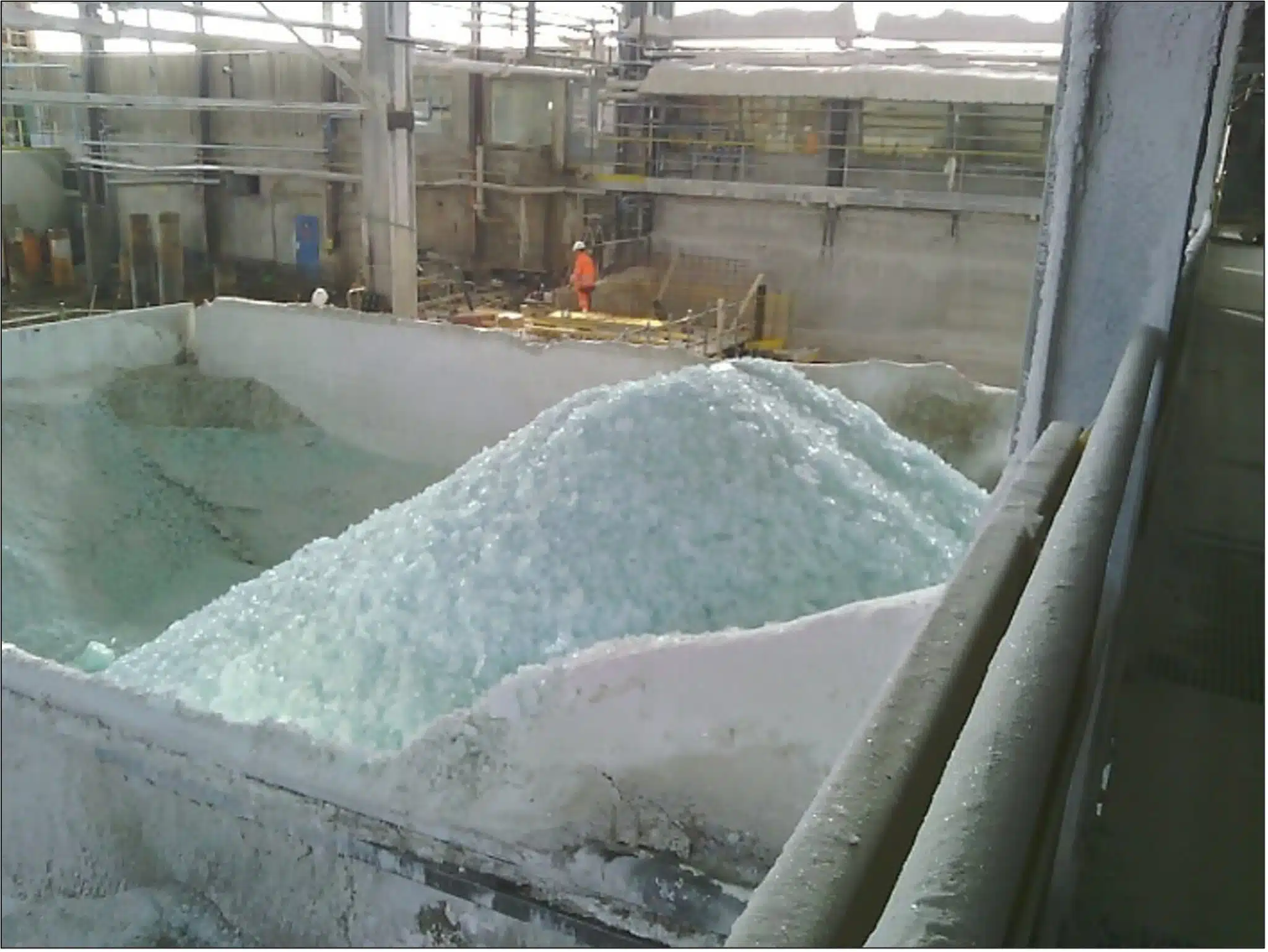
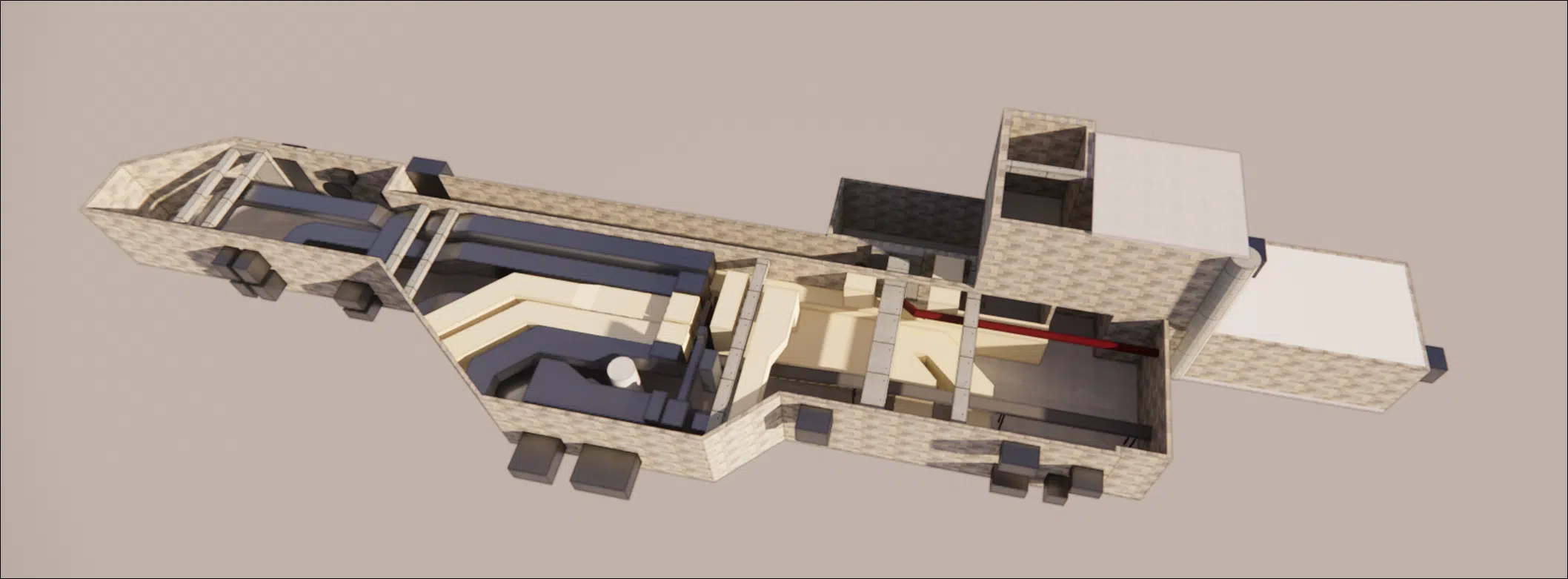
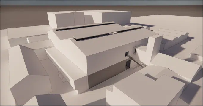
The CFD model was developed from the supplied plans, the photos taken during the audit and a detailed site survey. The aim was to faithfully represent the volumes, structures and equipment influencing the airflows and heat exchanges. The model notably incorporates the platforms, beams, cooling pits, openings to the outside, curtains, as well as the future installations planned around the electric furnace.
The numerical mesh, of hybrid type, reaches several tens of millions of cells, with local refinement in the critical zones: around the casting, under the platforms and at the blowing ducts. This level of detail ensures a faithful restitution of the thermal and airflow gradients, while guaranteeing the numerical stability of the calculation.
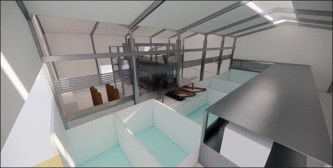
The boundary conditions were established from the audit data and the values supplied by the client. The main heat sources integrated into the calculation are the following:
The molten glass, modelled from 1200 °C to 300 °C along the length of the ingot mould.
The furnace walls, around 80 °C.
The pits, from 250 °C to 50 °C depending on the zone.
The moving equipment, such as the conveyors, around 70 °C.
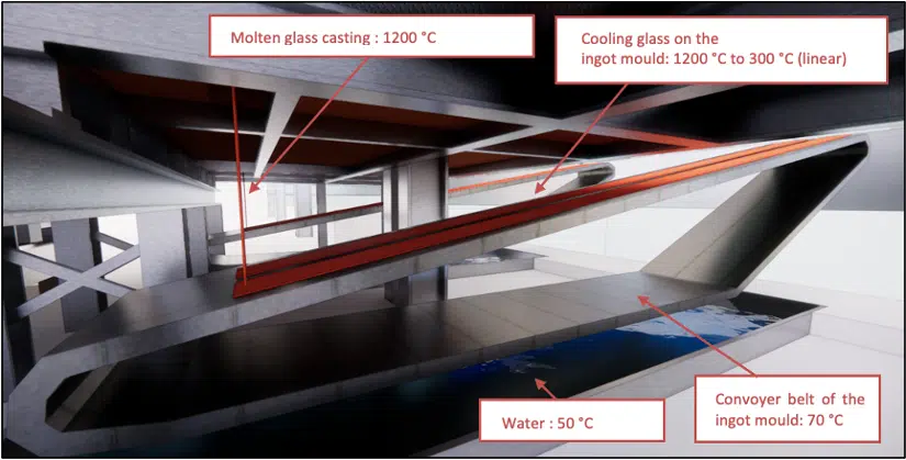
The convective exchanges with the walls, the nature of the materials (steel, silica, rock wool) and the outdoor temperature of 38 °C were integrated into the calculation. The simulation was carried out in steady state, allowing a stabilised reading of the temperature and air-velocity distributions across the whole building.
Several configurations were tested in order to compare different variants:
Presence or absence of insulation under the platforms.
Integration of radiation shields of various shapes (trapezoidal, flat, U-shaped).
Addition or not of localised fans.
Modification of the façade openings to improve the air sweep.
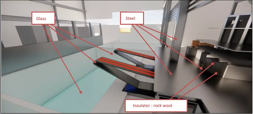
All of the simulations were carried out using an industrial CFD solver based on the Navier-Stokes equations, with a standard k-ε turbulence model, particularly suited to internal-ventilation environments. This model reproduces the phenomena of stratification, recirculation and acceleration of the air masses in complex geometries such as that of the studied site.
Particular care was taken over the convergence of the calculations, with a precision threshold of 10⁻⁴ on the residuals, guaranteeing the reliability of the results and the stability of the model.
The k-ε turbulence model resolves the turbulent kinetic energy and its dissipation; it is a robust standard for internal ventilation. In steady state, the calculation seeks the equilibrium of temperatures and velocities, without following their evolution over time.
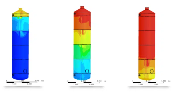
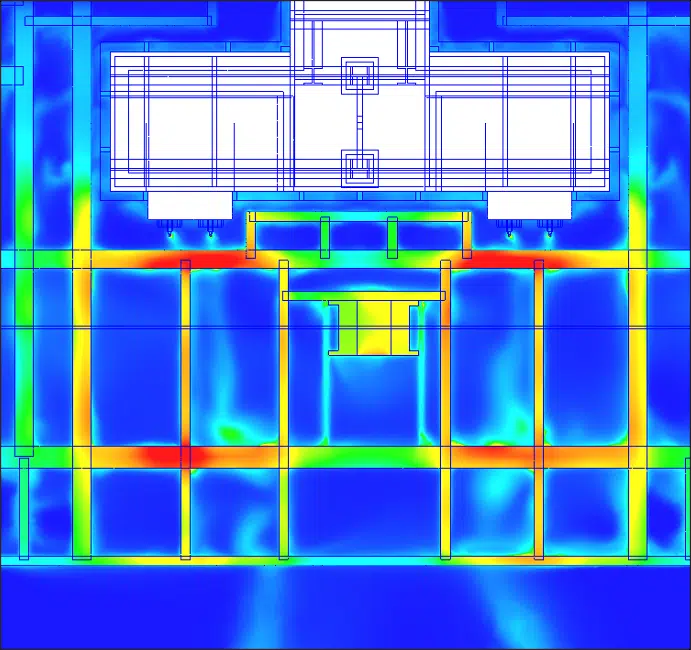
The simulations carried out around the new electric furnace highlighted a marked rise in temperatures in the zones located near the casting. The steel beams under the platform reach, in certain configurations, temperatures above 300 °C, particularly when the radiated hot air cannot escape freely.
Without a protection device, the most exposed beams are directly subject to the thermal radiation of the casting, with maximum values measured between 320 °C and 480 °C depending on the simulated cases. These temperatures exceed the design limits of certain structures, generating potential risks of deformation, loss of mechanical strength or excessive expansion.
A radiation shield is a screen, often polished aluminium with insulating reinforcement, placed between the hot source and the element to protect. It reflects most of the incident radiation and, in an inverted-U shape, guides the hot air towards dissipation zones away from the workstations.
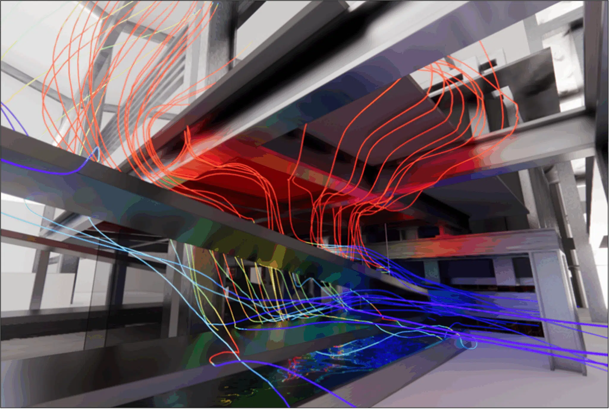
The study compared several design variants to limit this heating. In the cases where insulation is placed under the platform, the temperatures below it rise, due to a lower evacuation of the heat. Conversely, the addition of aluminium radiation shields with insulating reinforcement, placed between the casting and the beams, effectively protects the structure.
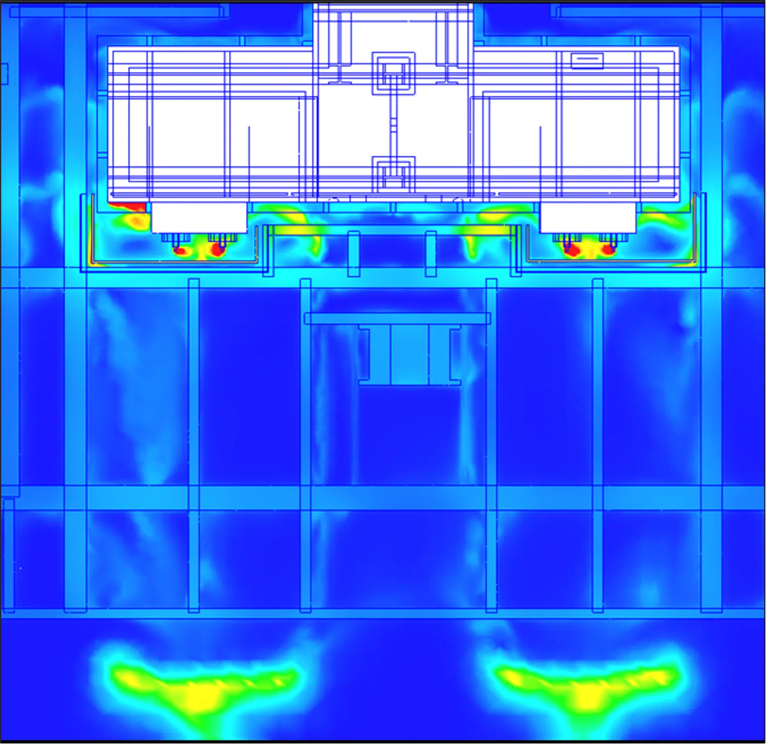
The configurations with a horizontal or U-shaped radiation shield show a significant temperature reduction, with beams brought below 160 °C, or even 100 °C in the protected zones.
Moreover, the shape of the radiation shield directly influences the orientation of the thermal flows: the inverted-U versions guide the hot air masses towards dissipation zones, away from the workstations. The solutions integrating thermal insulation on top of the radiation shields reduce the secondary radiation towards the structures and effectively protect the upper elements such as the grating or the conveyor arms.
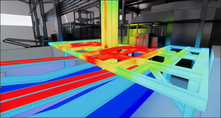
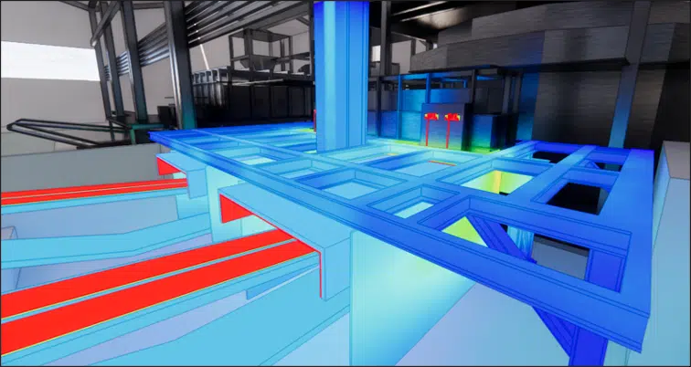
At the scale of the hall, the simulations revealed a significant thermal stratification, with temperatures varying from 38 °C to 52 °C between the floor and the roof. The most affected zones are located south of the furnace, in initially poorly ventilated areas where heat stagnation was observed. In these zones, the thermal delta can reach +12 °C compared to the outside, which impacts comfort and working conditions.
Adding a south-east façade opening, recommended by EOLIOS, made it possible to introduce a flow of fresh air in the simulations. This modification reduces the temperatures in the critical zone to around 43 °C and markedly improves the air circulation. In addition, thermal curtains positioned around the casting zones demonstrated their effectiveness in protecting the operators from direct radiation.
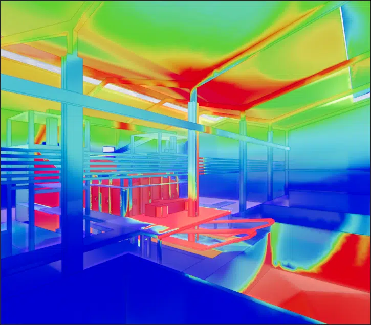
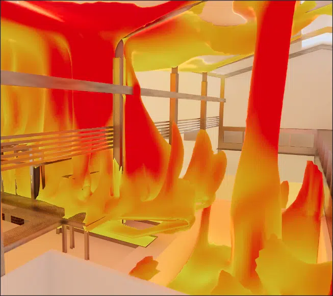
The final configuration, integrating all of the devices recommended by EOLIOS (U-shaped radiation shields with insulation, thermal curtains, localised fans, façade opening), makes it possible to bring the beam temperatures to levels compatible with their normal use, while ensuring acceptable atmospheres at personnel level.
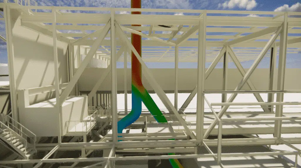
The results show beam temperatures below 100 °C in the majority of cases, with a few peaks at 115 to 150 °C in the zones closest to the casting spouts. The ambient air in the work zones is broadly close to the outdoor temperature (38 to 40 °C), and the thermal plumes are well channelled to the roof, far from the occupied workstations.
This balanced solution makes it possible to significantly reduce the thermal constraints on the structures while maintaining a good level of thermal comfort in the immediate environment of the process.
Key takeaway. On a very-high-temperature process, passive protection comes first: intercepting the radiation at the source (radiation shields) costs less and protects better than over-ventilating the whole hall. CFD is used to place these screens in the right spot and to check they do not trap the heat elsewhere.
Thanks to its expertise in thermo-airflow engineering and the implementation of advanced numerical-simulation tools (CFD), EOLIOS enabled the operator of the silica-production site to anticipate precisely the thermal effects linked to the installation of a new high-power electric furnace.
The study conducted highlighted the zones sensitive to heating and the complex airflow dynamics within the hall, while identifying concrete improvement levers to strengthen structural safety, operator comfort and equipment durability.
By proposing a global solution integrating optimised radiation shields, suitable natural and mechanical ventilation, and improved façade openings, EOLIOS helped to guarantee the success of the project within a controlled energy-transition approach. This intervention illustrates EOLIOS's ability to support industrial players in their most demanding projects, combining field analysis, high-level numerical modelling and applied engineering.
Project: study of the natural ventilation of a steelworks Know-how: thermo-airflow phenomena in industry Project: sizing of an industrial chimneyRadiation from the casting, heating of the structures and thermal comfort in a high-temperature production hall.
The molten glass at 1200 °C emits intense radiation that heats the beams above it at a distance, up to 320 to 480 °C simulated without protection, beyond their design limits. The risk is deformation and loss of mechanical strength. A related challenge was addressed on our natural ventilation of a steelworks project.
Placed between the casting and the beams, the aluminium radiation shields with insulating reinforcement reflect the radiation and protect the structure. The U-shaped configurations bring the beams below 160 °C, or even 100 °C in the protected zones, by guiding the hot air towards dissipation zones.
The hall shows a stratification of 38 to 52 °C between floor and roof. Adding a south-east façade opening introduces fresh air and brings the critical zone back to around 43 °C; thermal curtains around the casting protect the operators from direct radiation.
Thermographic camera surveys locate the hot zones (beams, casting, pits) and smoke tests visualise the airflows. Combined with geometric surveys using a laser measure, they calibrate the CFD model to the real conditions of the site.
The process runs continuously at near-constant conditions; the thermal and airflow equilibrium is enough to size the protections. Steady state, with a k-ε model and a residual convergence of 10⁻⁴, gives a stabilised reading of temperatures and velocities.
Explore our expertise, projects and technical papers to go further than the FAQ.
The thermo-airflow study carried out by EOLIOS made it possible to characterise the effects of the new electric furnace on the site environment, both on the structures and on the comfort of the operators. Thanks to detailed CFD modelling and a thorough field audit, the zones of heating, air stagnation and excessive radiation were identified. The proposed solutions — radiation shields, improved ventilation and thermal protections — ensure the safety of the structures, the control of the working atmospheres and the durability of the installations.
CFD expertise, delivered projects and technical dossiers: the whole Industrial process field in one place.
The simplest thing is to talk it through together. Our engineers reply with an initial technical read.