What is thermal draught?
Thermal draught, also known as the stack effect, is a physical phenomenon that occurs in buildings when the warm air inside, being less dense than the cold outside air, tends to rise.
This natural movement of air generates an upward current in enclosed spaces, creating an air flow that can be used for the natural ventilation of buildings. Thermal draught relies on the principles of buoyancy, where the temperature difference between the indoor and outdoor air produces a pressure difference. This pressure difference drives the warm air to escape through the high points of the building, while cold air enters through the lower openings.
The effectiveness of thermal draught depends on several factors, such as the building height, the temperature difference between inside and outside, and the configuration of the air inlet and outlet openings. This phenomenon is particularly relevant in high-rise buildings, where it can create significant challenges in terms of thermal comfort, energy consumption, and even safety. Understanding and mastering thermal draught is therefore essential to optimize the energy performance of buildings, reduce energy losses and ensure a comfortable, healthy indoor environment.
The thermal draught effect in high-rise buildings
The stack effect
The thermal draught effect is a major challenge for skyscrapers, but it can also be a significant factor for buildings of two storeys or more. The structure acts like a giant chimney, efficiently channelling warm air upward until it eventually leaves the structure entirely. Generally, these phenomena are encouraged by open stairwells serving all the levels of a building.
The stack effect occurs when the outdoor temperature is appreciably lower than the indoor temperature. Cold air is denser than warm air: when it enters the structure at the bottom, it displaces the warm air higher up. This creates an air flow that draws in more cold air and intensifies the draughts. The taller the structure, the stronger this air flow. This is why revolving doors were developed shortly after the first skyscrapers: the suction force at ground level was so strong in winter that people struggled to open the doors! This phenomenon is still found today with lifts, which sometimes connect the lower parts of the building with the roof zones for shaft ventilation. However, in the presence of wind, the draught becomes such that lift doors can become jammed or significant whistling appears in the airlocks of the lower levels.
The obvious problem is that the conditioned indoor air is lost, and therefore wastes energy. But another factor is that this problem can worsen over time. If the air flow is particularly strong, it puts pressure on the parasitic air inlets: the seals crack, leading to new vulnerabilities. With sustained pressure, these gaps can widen and spread, intensifying the air flow and accelerating the energy loss.
The stack effect works because the warm air has to go somewhere when it reaches the highest level of the building. In many cases, it escapes into the attic through cracked ceilings, sealing defects at the ductwork, recessed light fittings, or simply through excessive air permeability of the attic floor. Once the warm air reaches the top level, it escapes outside through the slightest vulnerability it can find.
The neutral pressure plane
The neutral pressure plane is an imaginary horizontal plane where the internal pressure equals the external atmospheric pressure. At this height, the pressure difference between inside and outside is zero: air neither enters nor leaves the building. The neutral pressure point depends on the building's HVAC systems, which pressurize or depressurize according to their distribution zone. For thermal draught to work properly, the position of the neutral pressure plane must be studied in advance in order to determine the position of the air inlets and outlets from the design stage. The air inlets must be positioned below the neutral pressure plane and the outlets above it, as shown in the diagram below.
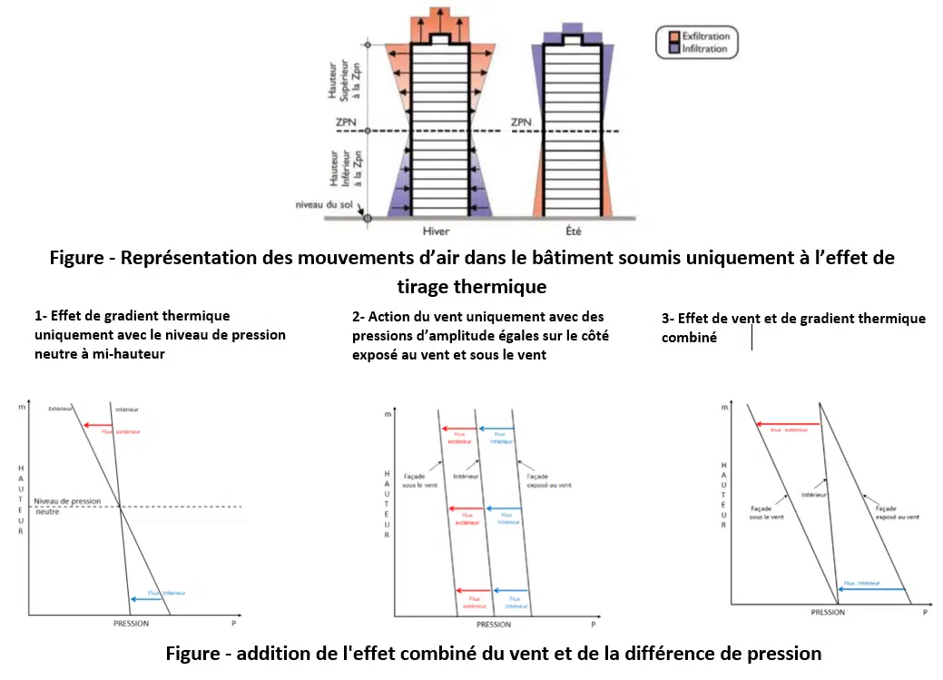
Indeed, below the neutral pressure plane, the indoor pressure is lower than the outdoor pressure: air enters the building. Above the neutral pressure plane, it is the opposite: the indoor pressure is higher than the outdoor pressure and air leaves the building.
Estimating the thermal draught in a building
Definitions and formulas
Buoyancy-driven ventilation exploits the principles of air-density difference to ensure an effective air renewal in an enclosed space. This method can be implemented in various ways, in particular through the combined use of cooling towers and chimneys.
Cooling towers, working on the principle of water evaporation to cool the air, supply cool air at the bottom of the space. When this cool air is heated by occupants or other internal sources, its density decreases and it becomes lighter, encouraging its rise. By means of a chimney, this warm, stale air is evacuated outside, creating an air current that allows cool air to continue entering through the lower openings to replace it.
The air-density difference depends on factors such as temperature and humidity. In winter, when the temperature difference between inside and outside is greatest, stack-effect ventilation is particularly effective. However, in summer, this method may not work effectively, because it requires the interior to be warmer than the exterior — which is generally undesirable during the hot months.
Buoyancy-driven ventilation, by exploiting the air-density differences due to temperature and humidity, can therefore be an effective method to ensure natural, comfortable ventilation of indoor spaces, but it requires adaptation to the climate conditions to be fully effective.
An expression for the ventilated air flow rate from the stack effect can be given by:
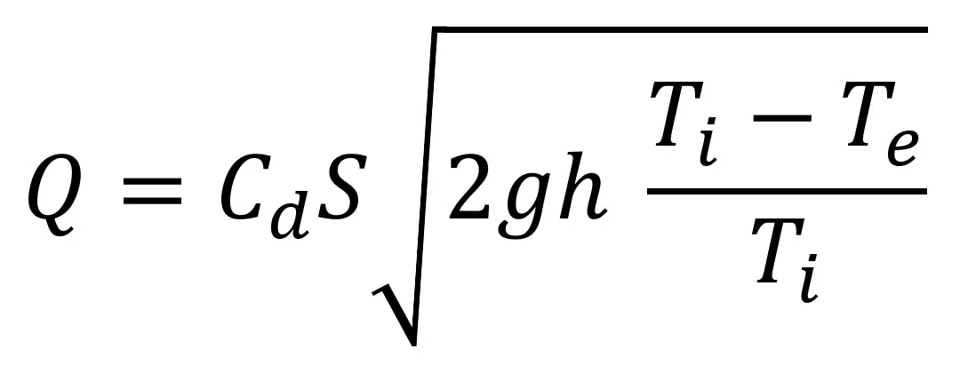
Where
- Q — the air flow rate ventilated by thermal draught
- Cd — the discharge coefficient
- S — the air passage section in the chimney (m²)
- g — the acceleration due to gravity
- h — the chimney height (m)
- Ti — the indoor temperature (K)
- Te — the outdoor temperature (K)
Note that the flow rate is positive when Ti > Te: the warm, stale air leaves the building. In summer, when Ti < Te, the flow rate becomes negative: warm air enters the building, which is not the intended effect. Thermal draught is therefore not suitable in cases of high outdoor temperatures for residential or office buildings. One can also note the case where Ti and Te are of the same order of magnitude (mid-season): the flow rate is then almost zero and there is no longer any ventilation. This is why, for conventional buildings, thermal draught is not suitable in all seasons.
Orders of magnitude
If we take the case of a residential building in winter with a 15 m tall chimney, the indoor temperature (Ti) is on average 20 °C and the outdoor temperature (Te) 0 °C. The discharge coefficient is taken to be roughly 0.65 and the chimney area (S) is 0.1 m². Carrying out the numerical application, the order of magnitude of the air flow rate ventilated by thermal draught is: Q = 0.34 m³/s, i.e. about 1200 m³/h. A chimney of this type makes it possible to properly ventilate (a flow of 5 air-changes/h) a space of 100 m². These values are only valid in the situation described above.
The discharge coefficient
The discharge coefficient is a parameter used to describe the performance of a chimney or duct in the context of thermal draught. It represents the fraction of the theoretical mass air-flow rate that is actually drawn through the duct due to the thermal draught effect.
The discharge coefficient depends on several factors: the geometry of the chimney, the roughness of its walls, the air temperature inside the duct, the temperature difference between inside and outside, as well as other environmental variables.
To compute it, one can use empirical models based on experiments and observations, or numerical simulations taking into account the various influencing variables. These models or simulations make it possible to determine the discharge coefficient for a specific chimney configuration under given conditions.
In general, the discharge coefficient is expressed as a value between 0 and 1, where 1 represents an optimal draught (all the theoretically available air is actually drawn through). A value below 1 indicates losses or inefficiencies in the draught process.
The contribution of CFD simulation
CFD simulation (Computational Fluid Dynamics) offers an undeniable advantage in determining the discharge coefficients of thermal draught. It provides a precise estimate that is more accessible than traditional experimental methods. Thanks to CFD, it is possible to virtually analyse the behaviour of air flows in a thermal-draught system, offering a deep understanding of the phenomena of convection and turbulence.
Moreover, this approach offers great flexibility in modifying and optimizing the project, since it intervenes at an early stage of the design — thus avoiding the costs and constraints of changes during the construction phase. CFD simulation directly accounts for the pressure-loss effects: thanks to the theoretical loss-free formula (Cd = 1), one can work back to the discharge coefficient of the studied system.
In short, CFD simulation is an essential tool for an effective, optimized design of thermal-draught systems.
Thermal draught in industry
The challenges
In an industrial environment, the thermal-draught phenomenon is of crucial importance. Often generated by equipment such as furnaces or machines, the heat to be evacuated is characterized by very high temperatures. These thermal conditions require effective management, as they can lead to a build-up of heat inside the industrial facilities.
Moreover, the temperature of the air to be evacuated is often markedly higher than that of the outside air, even in summer: thermal draught then works even during heatwaves. This thermal offset aggravates the challenges related to temperature control and ventilation, requiring specific solutions to maintain optimal working conditions and ensure the safety of industrial operations.
CFD simulation
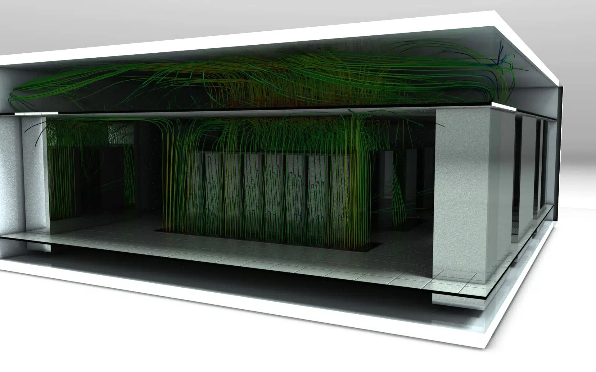
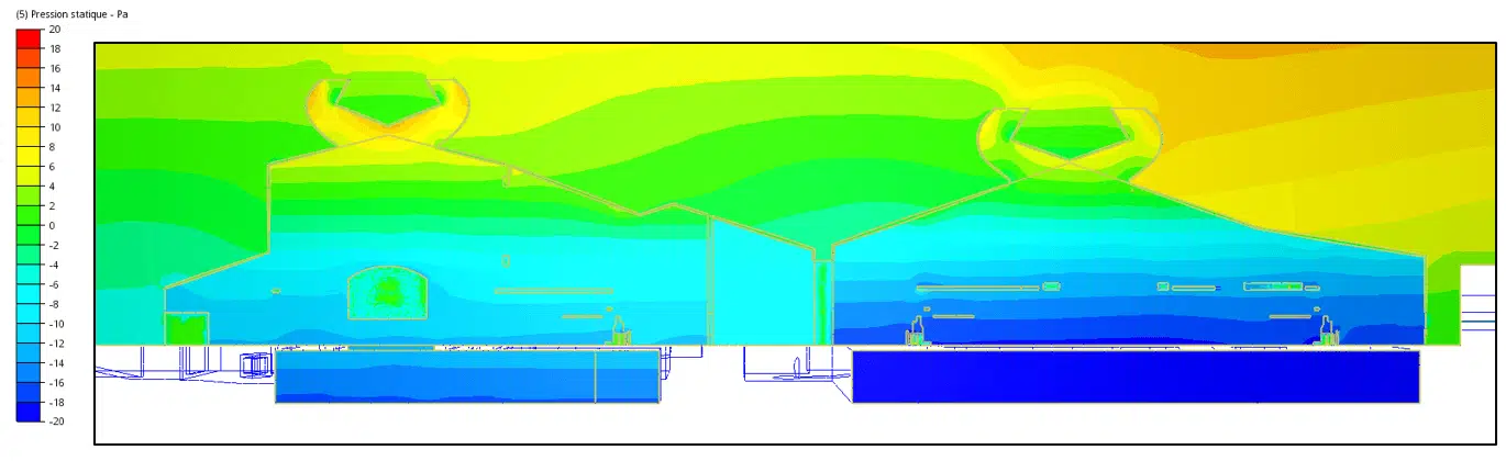
The two images below show a numerical simulation carried out for the ventilation of an industrial site, for which a sizing of static roof vents had to be performed.
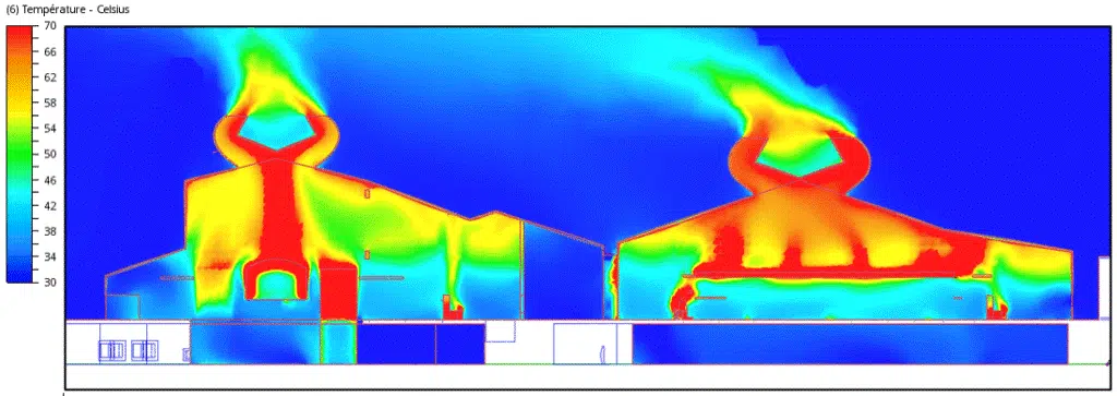
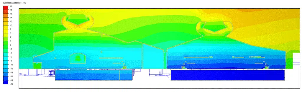
The sizing of natural-ventilation openings is strongly influenced by the neutral pressure concept. This designates a crucial level where the internal pressure of a space equals the external atmospheric pressure, forming a notional horizontal plane. At this level, the air-inlet openings are not very effective; above it, the internal pressure exceeds that of the outside, making the placement of the air-outlet openings there essential. Conversely, the air-inlet openings are always placed below the neutral plane, because they generate a depression zone. During design, it is essential to determine precisely the height of the neutral plane and to wisely distribute the available pressure difference between the inlet and outlet openings, taking flow losses into account. Depending on the season, the position of the neutral plane is not the same, as shown in the diagram below.
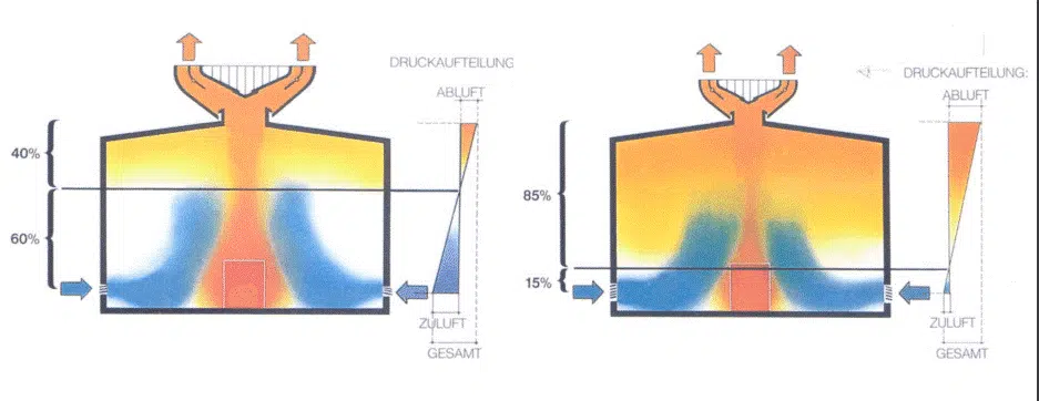
When the outdoor temperature is much lower than the indoor temperature (winter), the neutral pressure plane is located higher up. In summer, when the temperature differences are smaller — but still with a higher indoor temperature — the neutral pressure plane is located lower down. This is why, for the thermal draught to work in every season, the air inlets must be located below the minimum position of the neutral pressure plane, and the air outlets above its maximum position.
Conclusion
EOLIOS is therefore able to provide solutions in the field of chimney sizing, as well as openings and numerical simulations on thermal draught. Its expertise and know-how make it possible to offer precise, reliable modelling services and tools, to meet the needs of industries concerned with the energy efficiency and the safety of their facilities.
Sizing of openings, vents and ducts: our CFD engineers model your thermal draught.