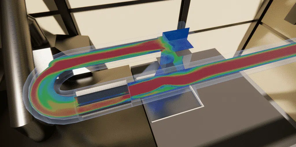
Design and pressure-loss calculations for the flue ducts of a laboratory: reducing pressure losses and eliminating condensation risks.
The main objective of this study is to understand and improve the performance of the flue ducts in combustion systems, with particular emphasis on reducing pressure losses and eliminating condensation risks. Flue ducts, if not properly designed, can create barriers in the flow, increasing the need for additional power to maintain the required flow rate, which leads to significant energy inefficiency. This issue is crucial because it affects not only operational efficiency but also the overall durability of the systems.
The essentials. For the LNE, EOLIOS sized a laboratory flue-duct network using CFD. The study targets two coupled challenges: lowering pressure losses (bends, baffles, narrowings) to save extraction energy, and keeping the wall above the dew point to avoid corrosive condensation. The route was optimised with gentle, uniform-diameter curves to preserve a laminar flow.
Furthermore, the build-up of condensation inside the ducts can cause corrosion problems, shortening the service life of the infrastructure. This makes it necessary to study in depth the thermal and fluid-dynamic behaviour within the ducts, in order to propose suitable design solutions that minimise these undesirable effects. Ultimately, the project aims to promote the safety and durability of fume-management systems.
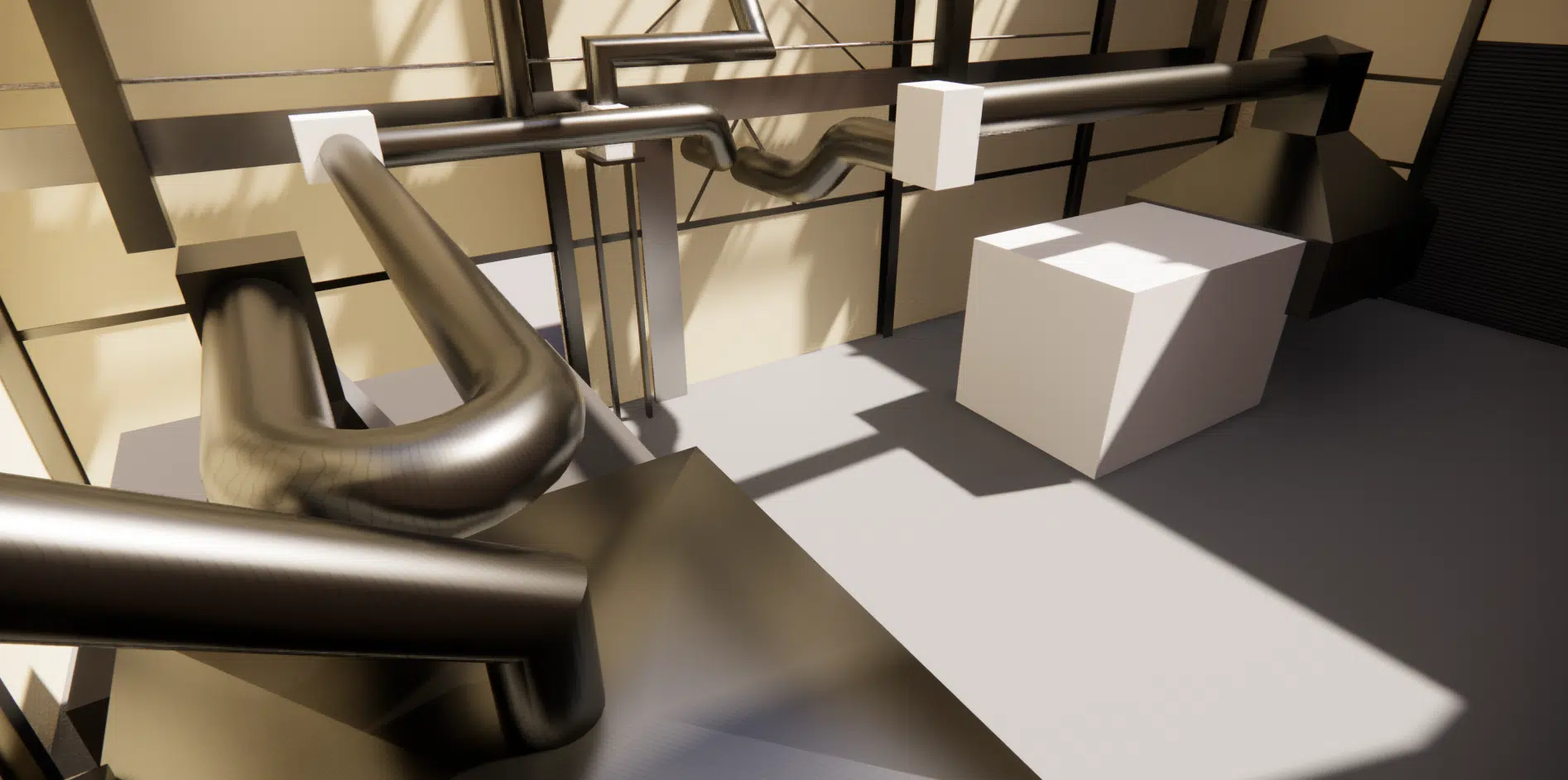
Flue ducts face a number of technical and operational constraints that must be taken into account to ensure optimal operation. Pressure losses are a major concern, as they represent the resistance the smoke must overcome to be extracted from the system, which often requires extra energy. These losses can be caused by structural features such as overly tight bends, abrupt narrowings or internal devices like baffles, which disturb the laminar flow of the fumes. Another critical constraint is the management of condensation inside the ducts.
Pressure loss is the drop in pressure a fluid undergoes as it flows: every bend, narrowing or obstacle dissipates part of it. Too high, and more energy is needed to maintain the flow rate. See the paper on pressure loss and hydraulic resistance.
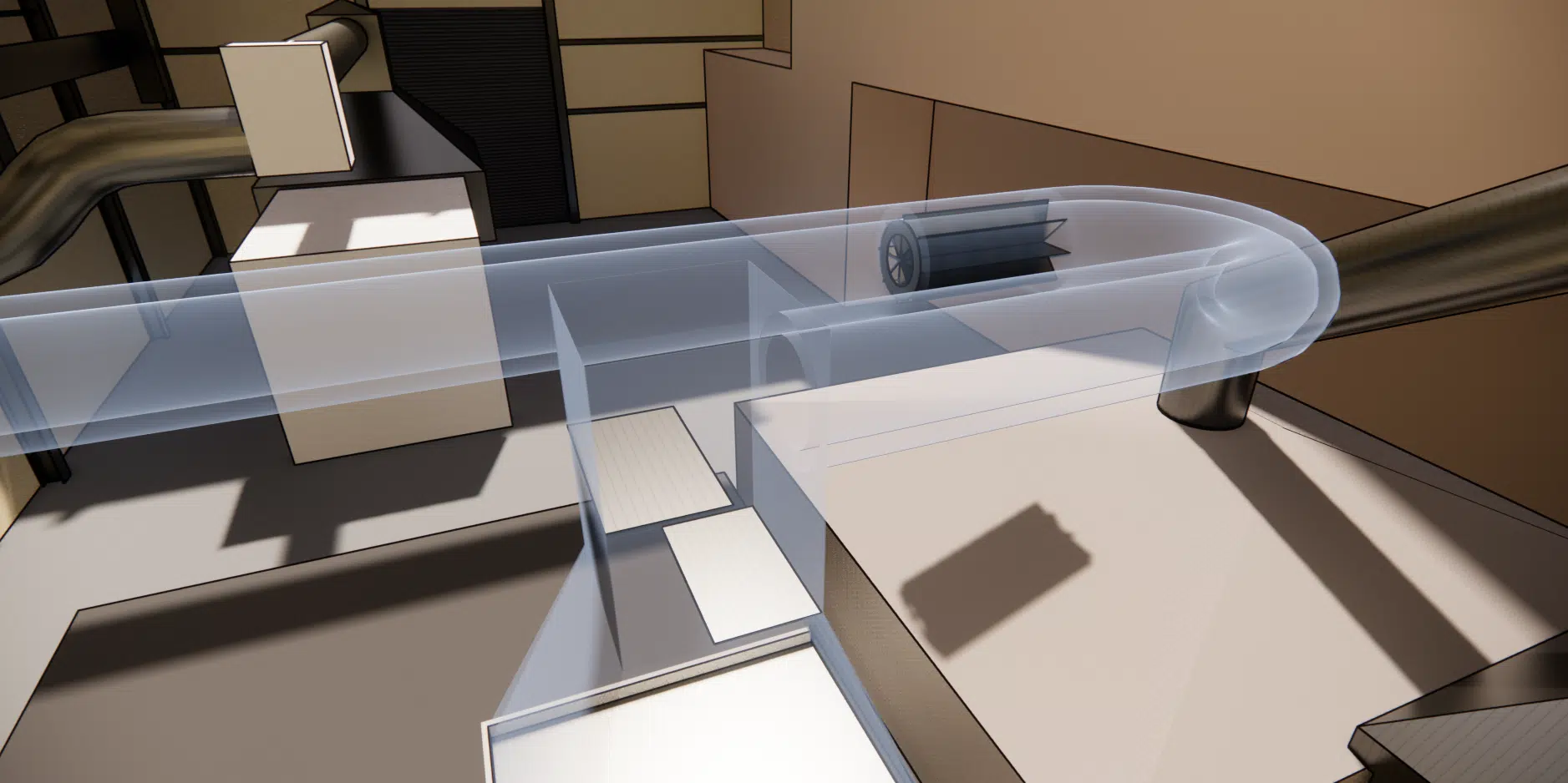
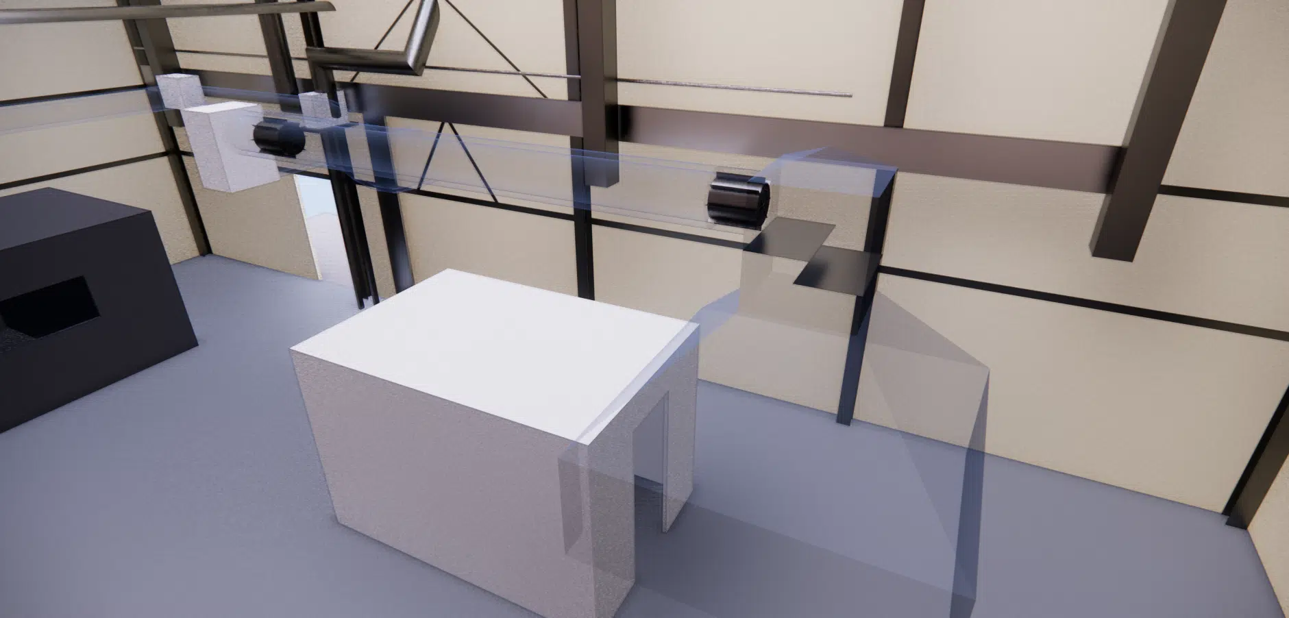
When temperatures drop below the dew point of the fumes, condensation can occur, leading to a build-up of potentially corrosive liquid. This not only damages the ducts but can also compromise the safety of the whole system. Industrial and regulatory standards also impose strict requirements on safety and durable performance to prevent these risks. Finally, practical constraints such as the limited space for installing the ducts, access for maintenance and compliance with local regulations can considerably influence the design and installation of the systems.
The dew point is the temperature at which the water vapour in the fumes begins to condense. If the duct wall drops below this threshold, an often-acidic liquid forms and corrodes the duct. The insulation is therefore sized to keep the wall above it.
To ensure the efficiency and reliability of the flue ducts, various technical and design criteria must be strictly observed. First, reducing pressure losses requires a design that favours the smoothest, most constant fume flow possible, minimising bend angles and avoiding obstacles in the flow path. This structural optimisation limits the need for additional energy to move the fumes, thereby reducing energy costs.
In addition, adequate thermal insulation is essential to keep the internal temperatures of the duct above the dew-point thresholds calculated for the various fume components. This helps prevent any form of condensation that could not only damage the ducts but also cause leaks and unexpected damage. The choice of materials is also crucial, requiring corrosion-resistant metals or coatings designed to withstand the acidic conditions potentially caused by the fumes.
Thermal draught is the natural driver of fume extraction: hotter and lighter, the fumes rise up the chimney and create a suction that draws the gases out. Excessive pressure losses or too cold a wall weaken this draught. See the thermal draught effect.
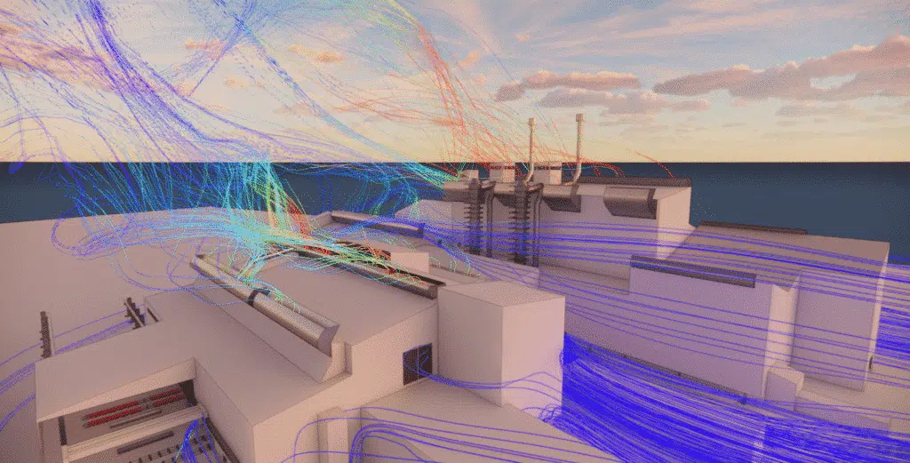
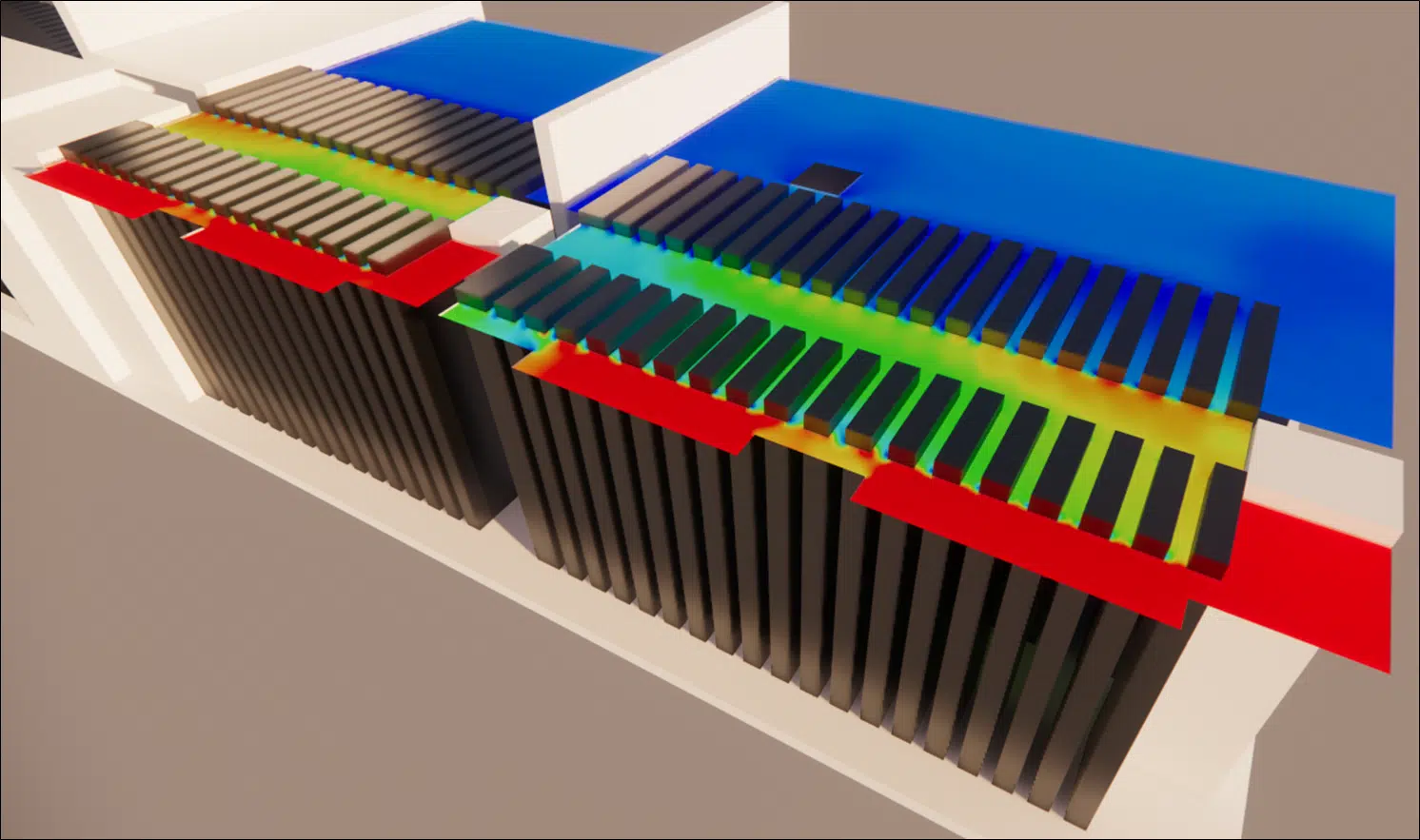
Computational fluid dynamics (CFD) modelling proves to be an indispensable tool for this study, providing analytical solutions to the complex challenges of fume management. CFD makes it possible to accurately recreate the internal conditions of the flue ducts, allowing a detailed visualisation of the fluid flows. Thanks to this technology, the impact of each design element on the pressure losses can be assessed, the configurations optimised to limit those losses, and the overall energy efficiency of the system thereby improved. The simulations can also predict the temperature variations along the duct walls, identifying the critical zones where the condensation risk is highest and making it possible to test interventions without the costs of building and installing a physical prototype.
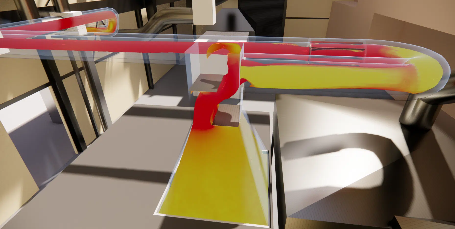
By providing valuable data on the dynamic behaviour of fluids, CFD makes it possible to explore different design scenarios before they are implemented, which considerably reduces the time and costs associated with developing new installations. Moreover, the ability to model duct performance under different operating conditions makes it possible to anticipate and mitigate potential failures before they occur, thereby contributing to the reliability and safety of the system.
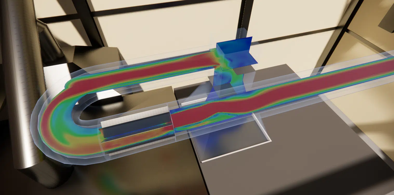
In designing the ducts, particular care was taken in choosing the route to minimise pressure losses. Optimising the path required a careful analysis of the possible configurations, taking into account the spatial constraints and the characteristics inherent to the installation sites. The bends were limited as far as possible, favouring gentle three-segment curves rather than sharp angles, in order to reduce the turbulence that increases flow resistance. The duct sections were designed to maintain a uniform diameter, avoiding abrupt narrowings liable to create bottlenecks. In addition, the consistent layout of the duct segments made it possible to optimise the overall routing, thereby reducing the total duct length and lowering the pressure losses associated with internal friction.
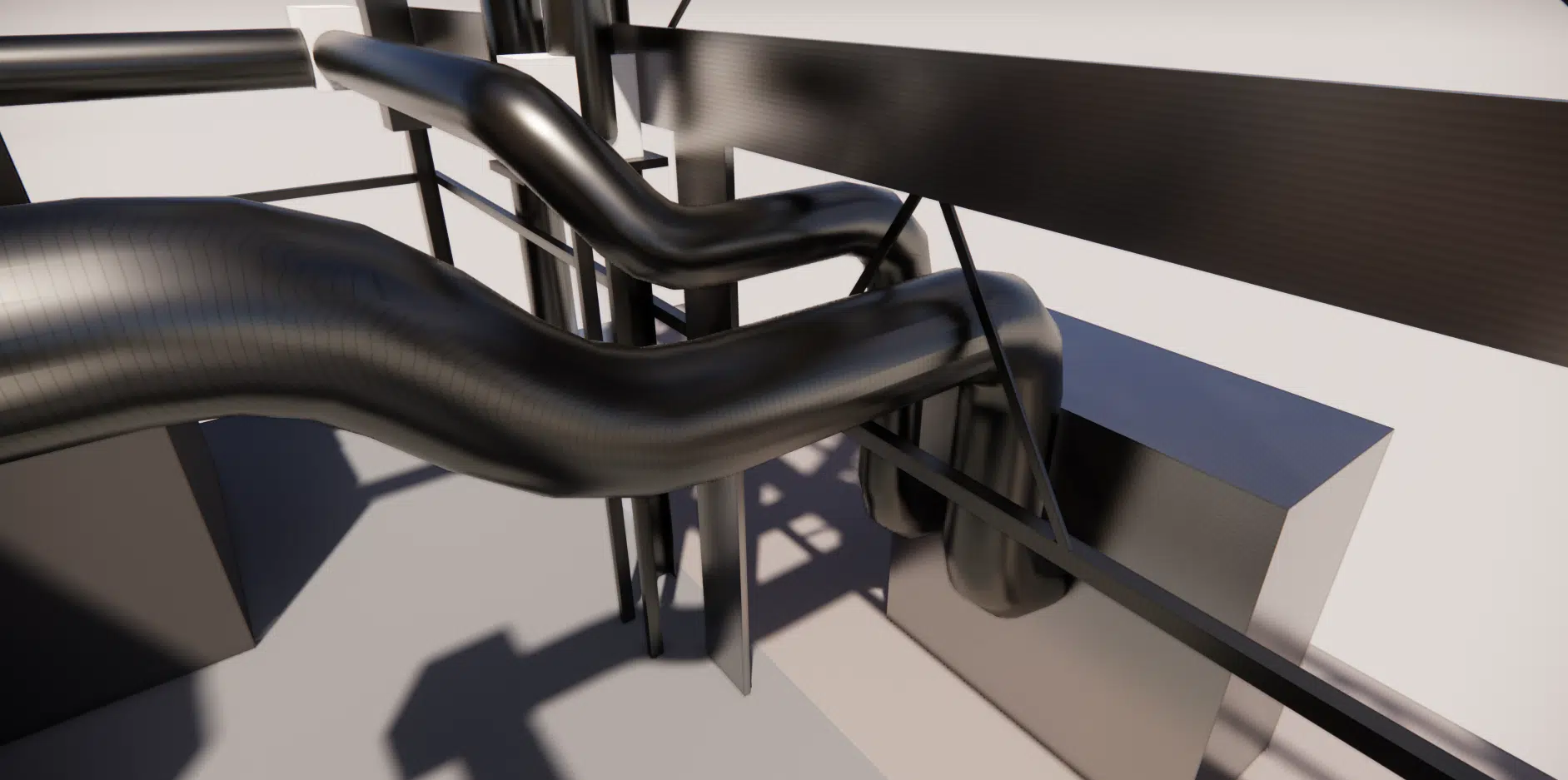
By integrating a CFD-based approach into the design process, simulations made it possible to identify the most efficient configurations, ensuring a continuous laminar flow while minimising the energy required to extract the fumes. Thanks to these design strategies, the proposed system not only meets the regulatory requirements but also improves the overall energy performance, thereby ensuring greater durability and efficiency of the installations.
EOLIOS is recognised for its advanced technical expertise and its ability to carry out flue-duct engineering projects with rigour. Drawing on extensive experience in CFD modelling, EOLIOS uses the latest technologies to analyse and optimise fume flows, ensuring the ducts are both efficient and compliant with the most demanding standards. EOLIOS's engineers and specialists have a deep understanding of fluid dynamics and thermal constraints, enabling them to propose innovative, tailored solutions that incorporate the best practices in the industry. This study extends our know-how on industrial chimney sizing.
Key takeaway. On a flue-duct network, two requirements pull in opposite directions: lowering pressure loss calls for opening up and shortening the path, while avoiding condensation calls for insulating and keeping the wall warm. CFD is precisely what finds the route that satisfies both.
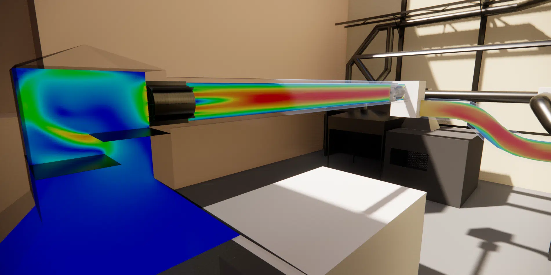
Pressure losses, condensation and route optimisation of a flue-duct network.
Every bend, narrowing or baffle resists the flow. The higher the pressure loss, the more energy is needed to maintain the extraction flow rate, which degrades the energy efficiency and reliability of the system. A related challenge was addressed on our CNIT pressure-loss project.
When the wall drops below the fumes' dew point, the vapour condenses into an often-acidic liquid. This liquid corrodes the duct and shortens its service life; sufficient insulation keeps the wall above the dew point.
You act on the geometry of the route: gentle three-segment curves rather than sharp angles, a uniform diameter with no abrupt narrowing, minimised total length. This preserves a laminar flow and lowers the resistance.
It visualises the real flow inside the duct, locates the turbulence and pressure-loss zones and predicts the wall temperature. Several routes are tested numerically before manufacturing, with no prototype cost.
A sharp angle separates the flow and creates highly dissipative eddies. A gentle three-segment curve guides the fumes progressively, reducing turbulence and therefore the local pressure loss.
Explore our expertise, projects and technical papers to go further than the FAQ.
Design and pressure-loss calculation of a laboratory flue-duct network (LNE): diagnosing the constraints (bends, baffles, dew-point condensation), design criteria (smooth flow, insulation, anti-corrosion materials), CFD modelling of flows and temperatures, and routing optimisation (gentle curves, uniform diameter) for a laminar flow and better energy performance.
CFD expertise, delivered projects and technical dossiers: the whole Industrial process field in one place.
The simplest thing is to talk it through together. Our engineers reply with an initial technical read.