
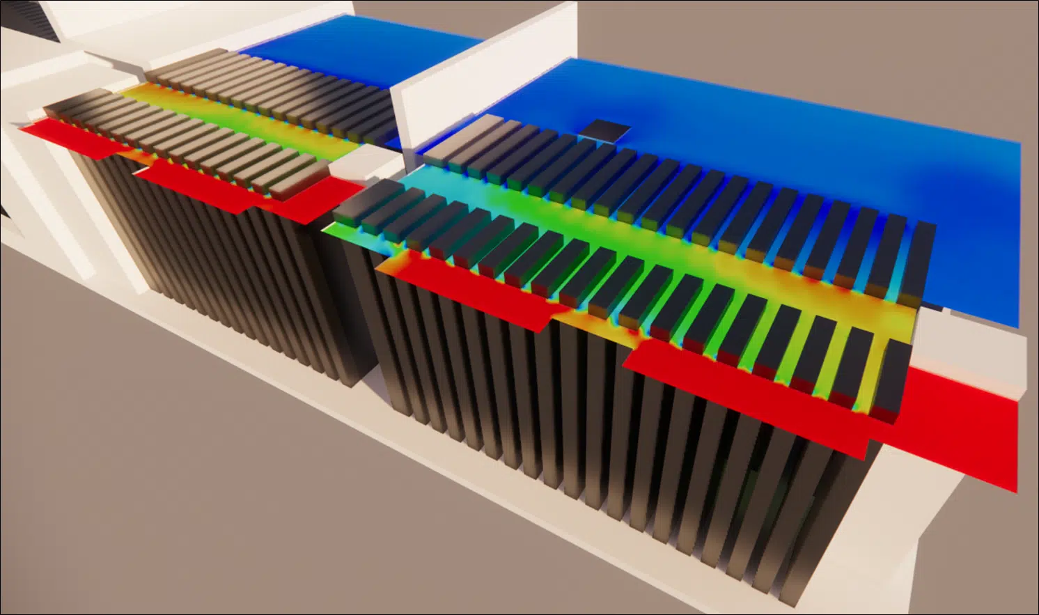
Optimise the performance of your generators by understanding the pressure losses in their rooms and their impact on the operational continuity of your data center.
The generators are a data center's last line of defence in the event of a main-power failure. A thorough study of the pressure losses in their rooms is essential to guarantee their availability and reliability.
The essentials. CFD study of the pressure losses in the generator rooms of a data center in Marcoussis. The acoustic sound attenuators, essential against noise, generate significant pressure losses; by revising the ducts and adding deflectors, the study reduced these losses by more than 50%, which speeds up the rooftop discharge and lowers the risk of short-circuiting with the dry coolers.
In a data center, the generators are the last line of defence in the event of a main-power failure. Their optimal operation guarantees the continuity of operations even during a power cut.
However, the performance of these generators can be compromised by several factors, notably the pressure losses in the rooms where they are installed. A thorough study is therefore of paramount importance to ensure the availability and reliability of the generators, and by extension, of the data center as a whole.
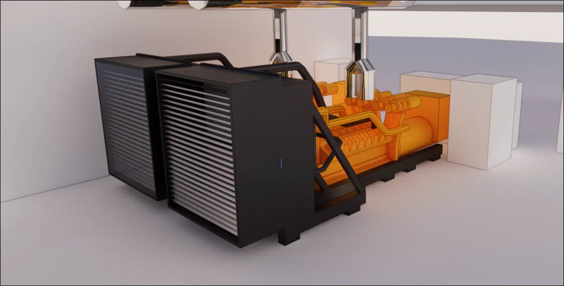
The energy of a volume of air is expressed as a sum of pressures, making up the total pressure:
Pressure due to the weight of the air column: ρgh.
Dynamic pressure linked to the air velocity: ρv²/2.
Static pressure linked to the internal pressure of the air: P.
The pressure loss of a component is the difference between the total pressures at its inlet and its outlet. It is due to the resistances encountered by the air through the elements of the network (ducts, bends, dampers, grilles…). On the generators, sound attenuators installed upstream and downstream limit the noise nuisance, but generate significant additional pressure losses.
Sum of the static pressure, the dynamic pressure (linked to velocity) and the pressure due to the weight of the air column. A component's pressure loss is the difference in total pressure between its inlet and its outlet.
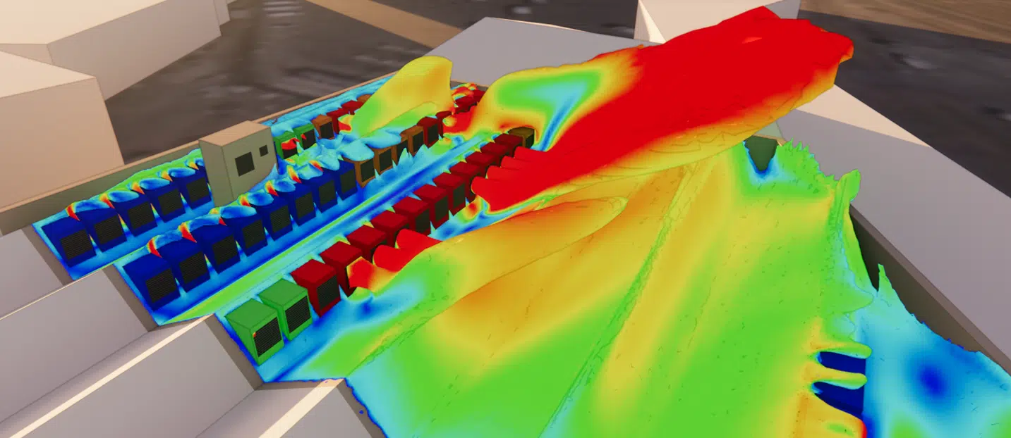
Pressure-loss CFD studies allow detailed numerical modelling of the flows and provide crucial information on the pressure-loss, turbulence and stagnation zones. They make it possible to identify the weak points, optimise the design and predict the effect of modifications before their physical implementation, an economical method.
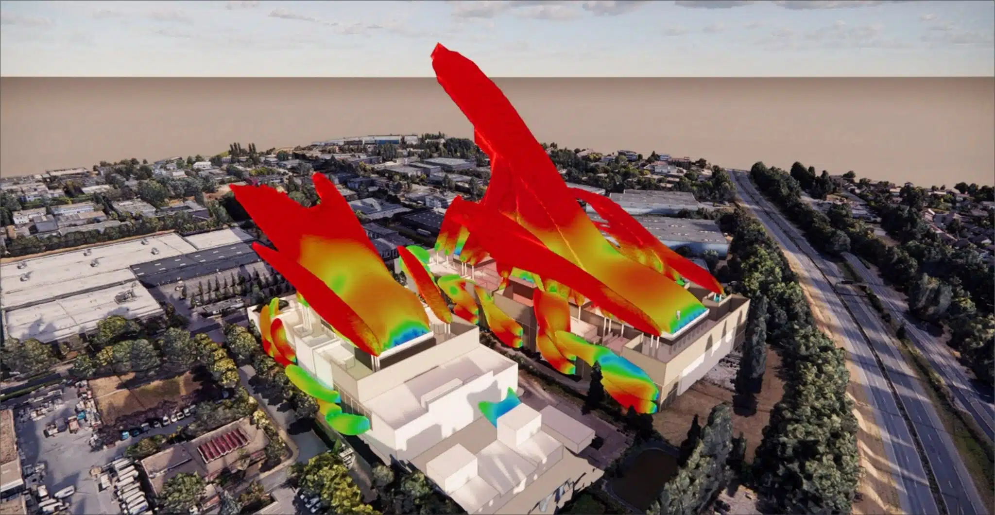
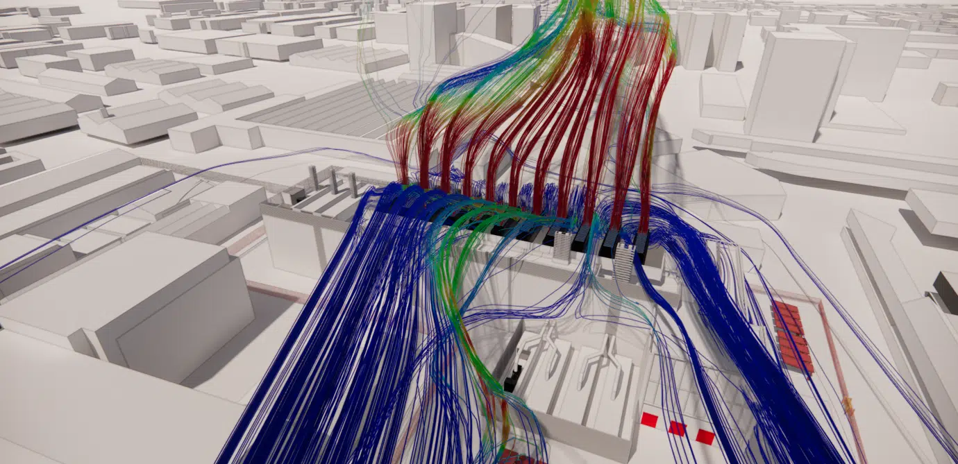
Key takeaway. Reducing the pressure losses makes it possible to achieve higher discharge velocities on the roof, and therefore to reduce the risk of short-circuiting with the dry coolers.
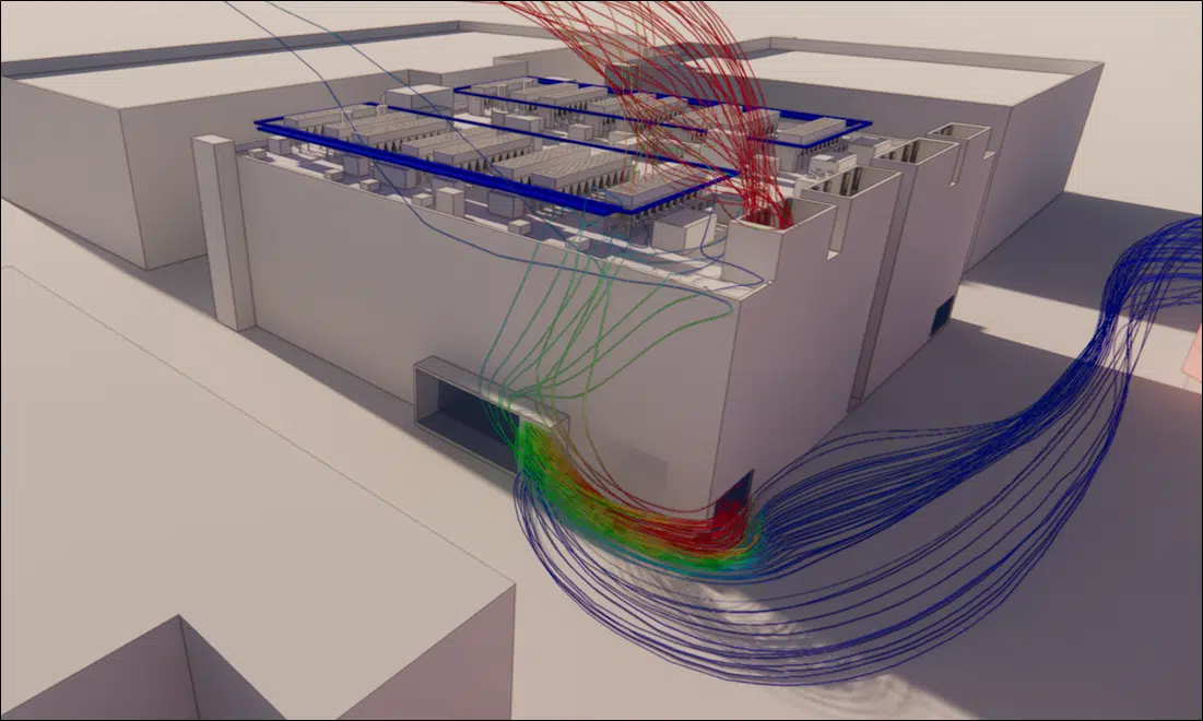
Most of the pressure losses in the generator extraction lines are singular pressure losses, caused by abrupt changes in geometry (bends, contractions, expansions):
Formation of vortices and turbulence zones — abrupt changes disturb the flow and cause energy losses.
Acceleration and deceleration of the flow — the passage between wide and narrow sections converts kinetic energy into pressure.
Wall friction — surface irregularities increase the resistance to flow.
These losses can be reduced through a suitable design of the ducts: smooth connections and gradual transitions between sections.
A localised energy loss caused by an abrupt change in geometry (bend, contraction, expansion) that creates vortices and turbulence, as opposed to distributed losses due to friction along the walls.
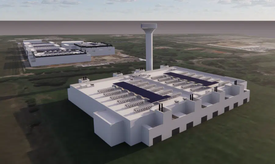
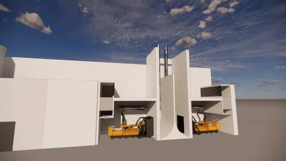
The 3D model of the technical room was created from the plans and the 3D model of the process: generators, sound attenuators, stacks, ducts and plenums were faithfully represented, respecting their actual location.
The velocities and pressures from the simulations are analysed to calculate the pressure losses of each room, by assessing the variations in total pressure along the air path.
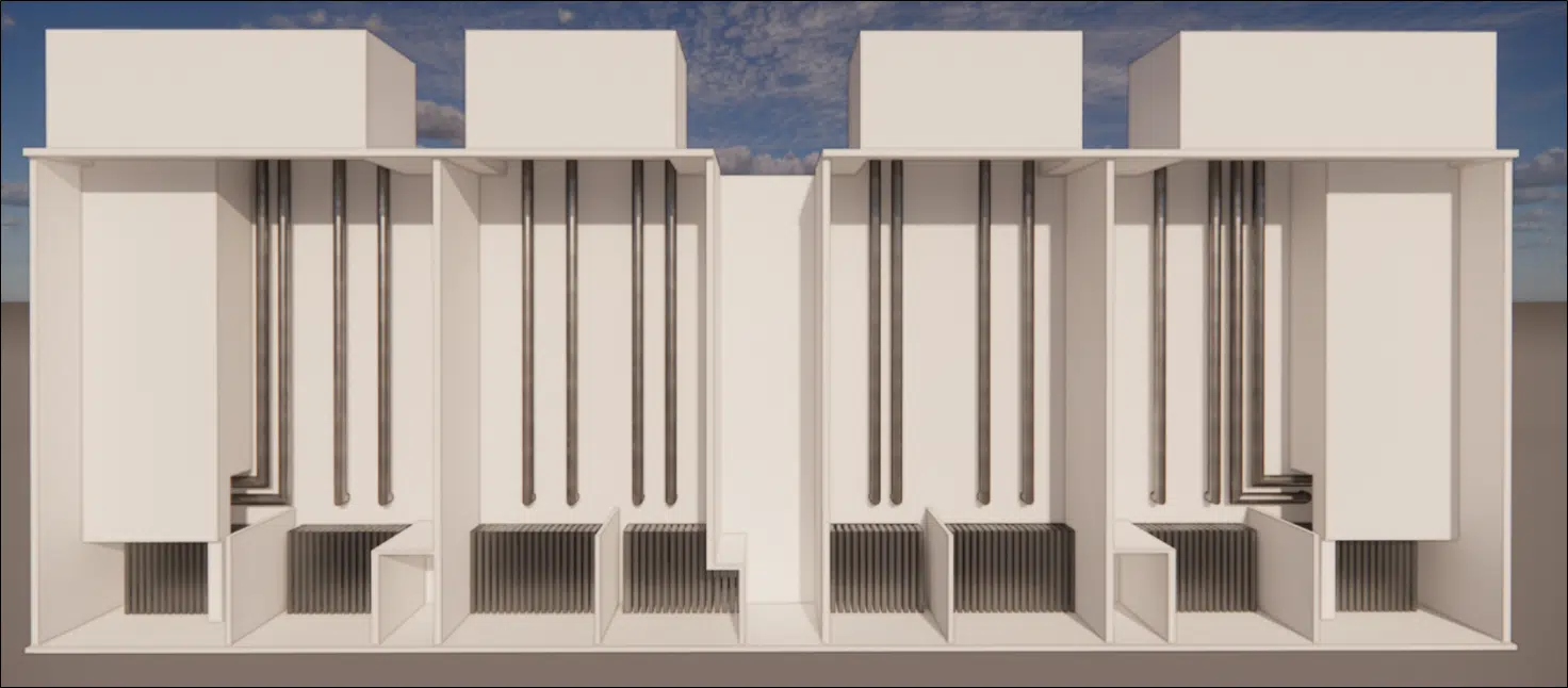
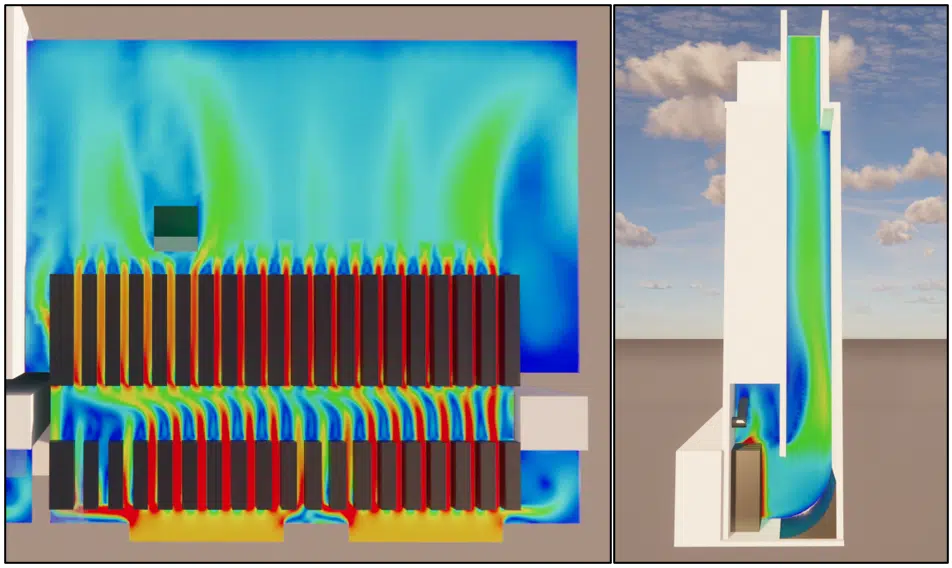
The sound attenuators considerably reduce the decibel level at the duct outlet. But the passage of air through these devices increases the pressure losses (obstruction, abrupt changes in direction, turbulence). It is therefore necessary to strike the right balance between acoustic reduction and pressure-loss reduction.
A baffle-type absorptive device placed upstream and downstream of the generator to attenuate noise. Effective acoustically, it obstructs the flow and adds pressure losses that must be balanced.
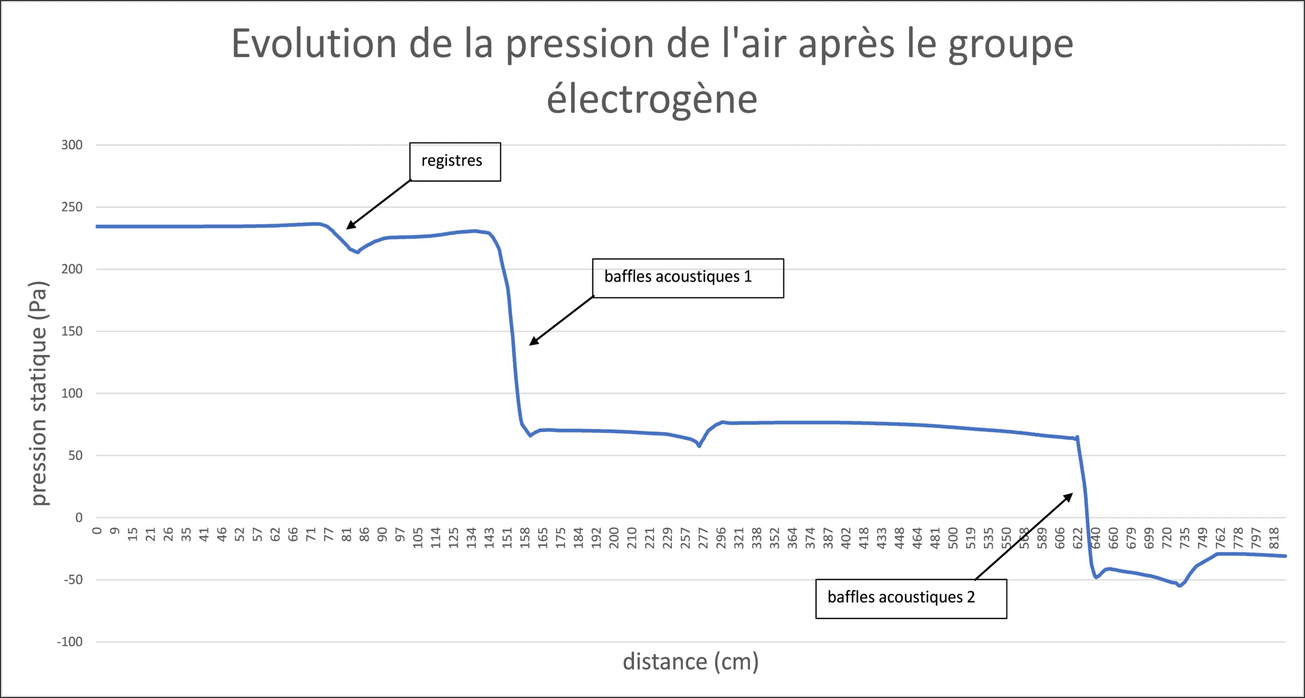
The configuration of the rooms caused excessive pressure losses. They were modified to reduce the resistance to flow, notably at the sound attenuators and the discharge duct. Deflectors were installed to make the changes of direction less abrupt.
Thanks to these modifications, the pressure losses were reduced by more than 50%. This reduction ensures efficient operation of the generators and allows higher air velocities at the duct outlet, reducing the short-circuit phenomena with the rooftop dry coolers.
Know-how: external CFD simulation for data centersSound attenuators, singular losses and duct optimisation: answers to the questions asked by operators and design teams.
Because the generators are the data center's last line of defence: excessive pressure losses compromise their air flow and therefore their reliability. CFD quantifies them and guides the optimisation, as on our project Data Center PA 22.
A localised energy loss caused by an abrupt change in geometry (bend, contraction, expansion) that generates vortices and turbulence. It dominates in the generator extraction lines.
They attenuate the noise with baffles, but obstruct the air passage and impose changes of direction, which creates turbulence and resistance. Acoustic reduction and pressure losses must be balanced.
By revising the geometry of the ducts at the sound attenuators and the discharge duct, and installing deflectors to soften the changes of direction. The losses were thus reduced by more than 50%.
Lower pressure losses mean higher discharge velocities at the duct outlet. The plume is projected higher and further, which reduces the risk of re-ingestion by the neighbouring dry coolers.
Explore our expertise, projects and technical papers to go further than the FAQ.
CFD study of the pressure losses in the generator rooms: 3D modelling of the ducts and sound attenuators, analysis of the velocities and pressures, optimisation reducing the losses by more than 50%.
 Digital twinData center study – Data Hall and UPS rooms
 Smoke controlSmoke-control engineering in a data center
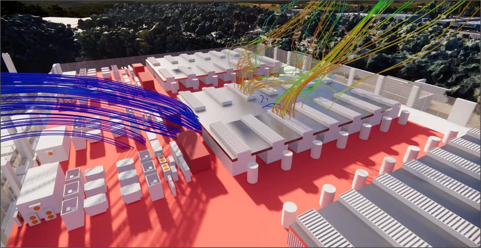 HyperscaleExternal & internal CFD – Hyperscale Data Center
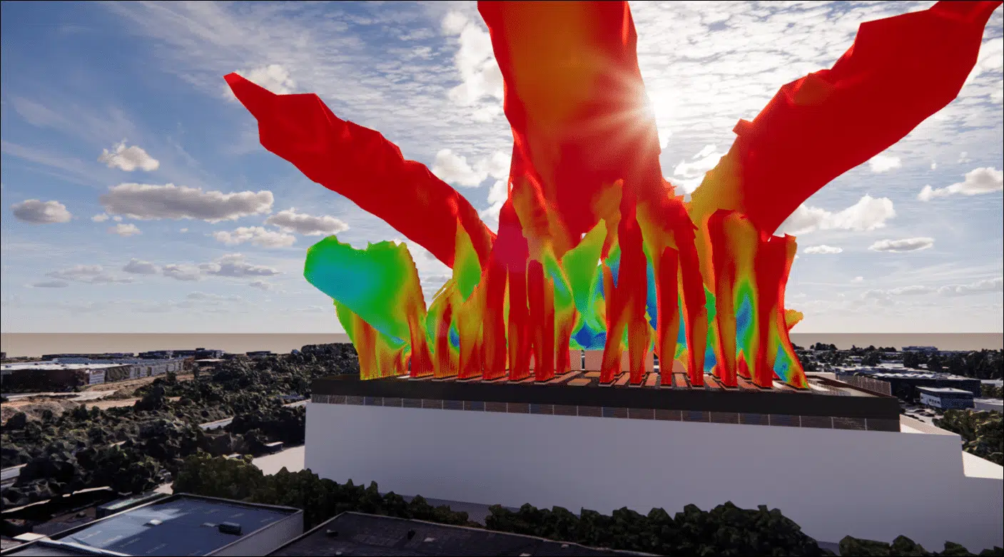 OptimisationCFD optimisation – Data Center
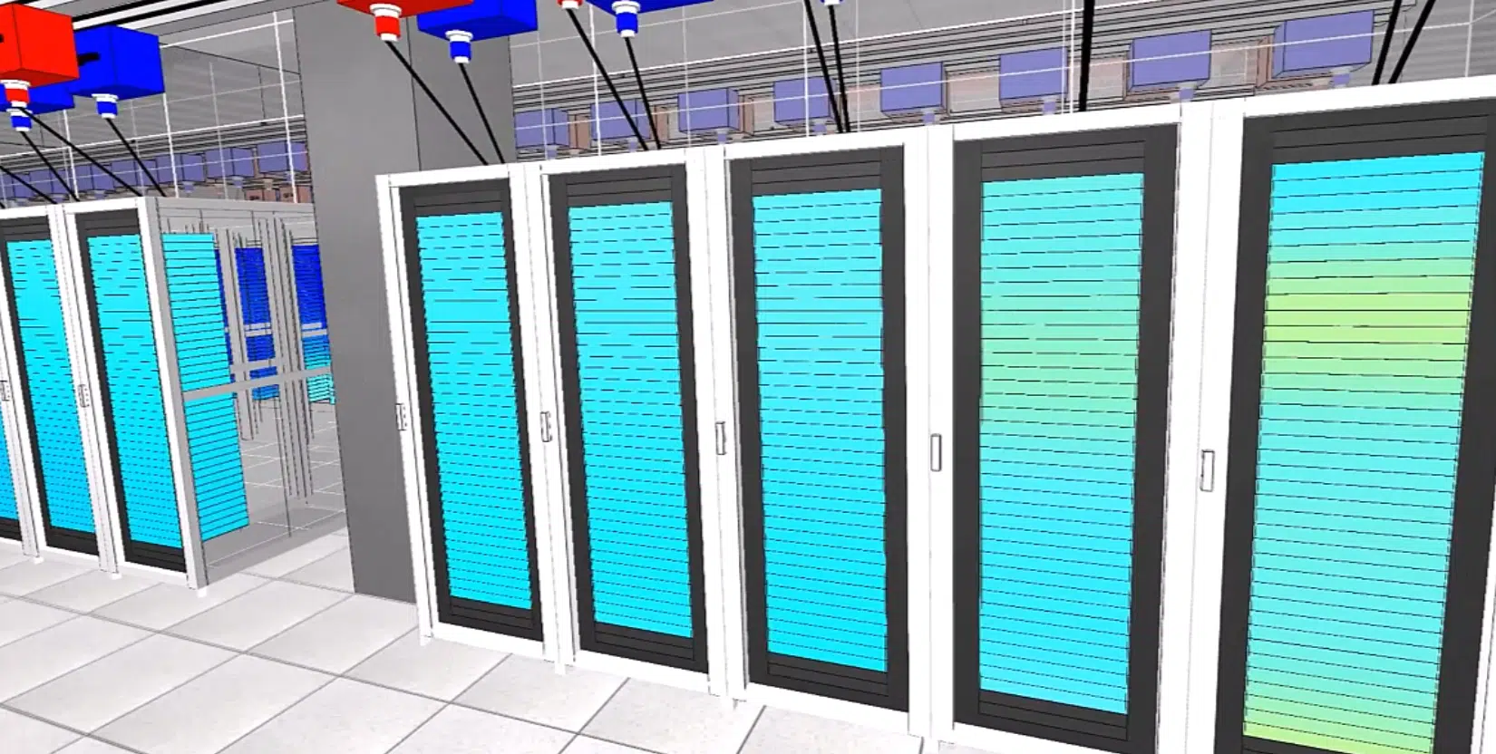 InternalData Center – DC28 – Internal
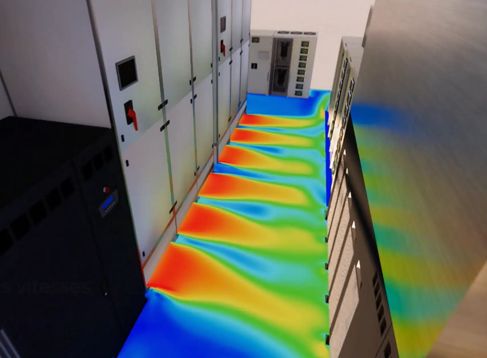 Technical roomsTechnical rooms – Data Center
 CoolingCooling optimisation – Data Center
 ExternalData Centers – DC15.1 & DC15.2 – External
 ExternalData Center – PA 22 – External
 ExternalData Center – Paris
 FireData Center – NOVEC gas
 InternalData center – DC17 – Internal
 ExternalData center – D14 – External
 ExternalData center – DC25 & DC26 – External
 InternalData Center – DC10 – Internal
 InternalData center – DC25 – Internal
ExternalData Center – DC25 & DC26 – External
InternalData center – DC25 – Internal
ExternalData Center – DC25 & DC26 – External
CFD expertise, delivered projects and technical dossiers: the whole Data Center field in one place.