The challenge of cooling data centers
Cooling data centers is a strategic challenge, directly affecting their energy efficiency, reliability and environmental impact.
Optimised thermal management makes it possible to avoid overheating of the IT equipment, reduce energy consumption and minimise the risk of interruptions. As fluid-mechanics experts, we combine CFD simulation, energy analysis and thermal-flow optimisation to guide operators towards high-performance, sustainable cooling solutions.
Heat production by IT equipment
Data centers house a multitude of servers and equipment running continuously; this incessant activity generates a significant amount of heat. Each electronic component — processors, memory modules, storage units — produces heat while operating, the result of the energy losses inherent in computing and data processing.
The power density in modern data centers can reach several kilowatts per square metre. According to one study, data centers consume up to 50 times more energy per unit of floor area than a standard commercial building. In 2017, their consumption represented 19% of the global consumption of the digital sector — consumption that translates directly into a proportional heat emission.
The consequences of poor thermal management
Main impacts
- Component overheating — malfunctions, computing errors and hardware failures; exceeding the operating range reduces reliability and performance.
- Increased energy consumption — cooling systems compensate for any uncontrolled rise; they account for nearly 40% of a data center's total consumption.
- Reduced lifespan — prolonged exposure to high temperatures accelerates component ageing and increases replacement costs.
- Higher operating costs — service interruptions, unplanned repairs and investment in higher-performance solutions.
The objectives of an efficient cooling system
Key objectives
- Stable, uniform temperature — generally between 18 and 27 °C; an even distribution prevents hot spots.
- Optimisation of energy efficiency — reduce consumption through advanced technologies (free cooling, liquid cooling).
- Reduced environmental footprint — minimise water and energy use; recover surplus heat (heating adjacent buildings).
Thermal management of data centers is therefore a crucial challenge that directly affects their performance, sustainability and environmental impact. Implementing suitable, efficient systems is essential in the face of the growing energy density of digital infrastructures.
Fundamental principles of cooling
The need for suitable cooling
Data centers are infrastructures essential to storing and processing digital data. Their continuous operation generates a significant amount of heat, mainly due to the high equipment density. Effective thermal management is crucial for the performance, reliability and longevity of this equipment.
Heat-transfer mechanisms
Conduction
- Transfer through solid materials (components, server structures), from hot zones to cold zones by direct contact.
Convection
- Heat movement via fluids (air): hot air from the servers is removed and replaced by cooler air.
Radiation
- Hot surfaces emit infrared radiation; less predominant, it contributes to the overall dissipation.
Organising airflow: hot and cold aisles
A common strategy is to organise the room into hot and cold aisles to separate the flows and prevent their mixing, improving cooling efficiency.
Cold aisles
- Made up of the front faces of the racks, where cool air is blown in to cool the equipment.
Hot aisles
- Located at the rear of the racks, they collect the hot air expelled after cooling.
By alternating and containing these aisles with physical barriers, the mixing of airflows is limited: this keeps lower temperatures at the server inlets and reduces the load on the air-conditioning systems. Using raised floors with perforated tiles makes it easier to distribute the cool air evenly.
Pressure differential between aisles: a major cause of hot spots
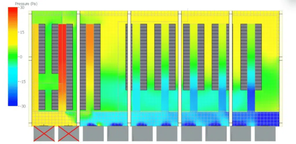
Beyond simply separating the flows, it is the balance of pressures between the cold aisle and the hot aisle that truly determines cooling efficiency. Air always flows from the high-pressure zone to the low-pressure zone: for each server to be properly supplied, the cold aisle must be kept at a slight overpressure relative to the hot aisle, of the order of a few pascals. This overpressure ensures that the cool air passes through the racks rather than bypassing them.
When this differential degrades — poorly distributed CRAC/CRAH unit flow, an under-pressurised plenum, badly positioned perforated tiles or partially empty racks without blanking plates —, two phenomena appear. Bypass: cold air goes straight to the hot aisle without cooling the servers, wasting energy. Recirculation: conversely, hot air flows back over or around the racks towards the air inlets, particularly at the top of the cabinets, where the supply pressure is lowest. It is precisely in these places that hot spots arise, those localised zones where the temperature exceeds the ASHRAE recommendations.
Mapping pressure to track down hot spots
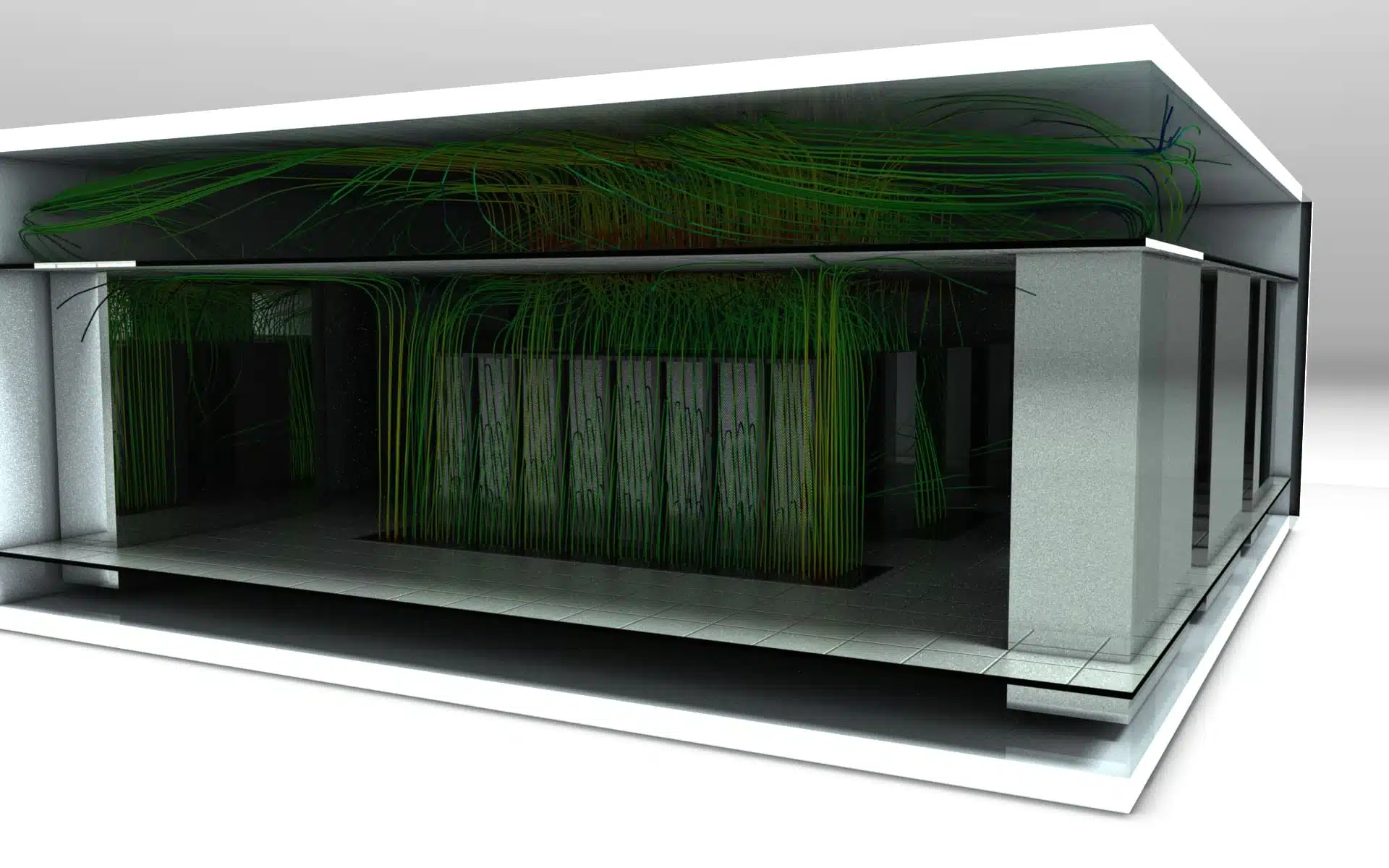
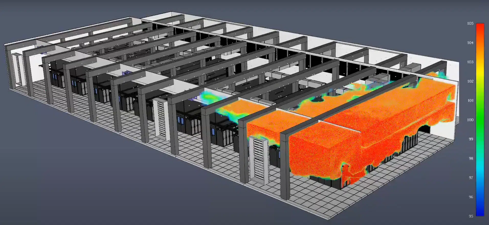
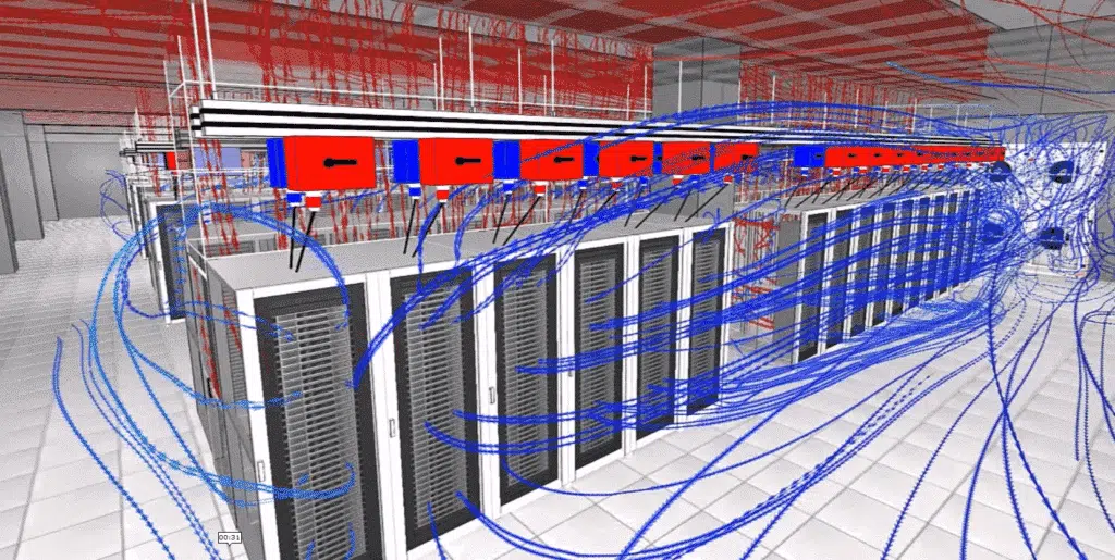
CFD simulation reconstructs the complete pressure field of the room: it reveals the low-pressure zones at the cabinet inlets, quantifies the bypass and recirculation flow rates, and makes it possible to rebalance the pressures (tile adjustment, containment, blanking of free Us) even before going into operation.
Recommended temperatures and humidity
Maintaining appropriate environmental conditions is essential. ASHRAE (American Society of Heating, Refrigerating and Air-Conditioning Engineers) provides precise guidelines:
ASHRAE recommendations
- Temperature — range of 18 to 27 °C for class A1 to A4 equipment, balancing energy efficiency and reliability.
- Relative humidity — between 20% and 80%, with a maximum dew point of 22 °C: humidity that is too low causes electrostatic discharges, too high causes condensation and corrosion.
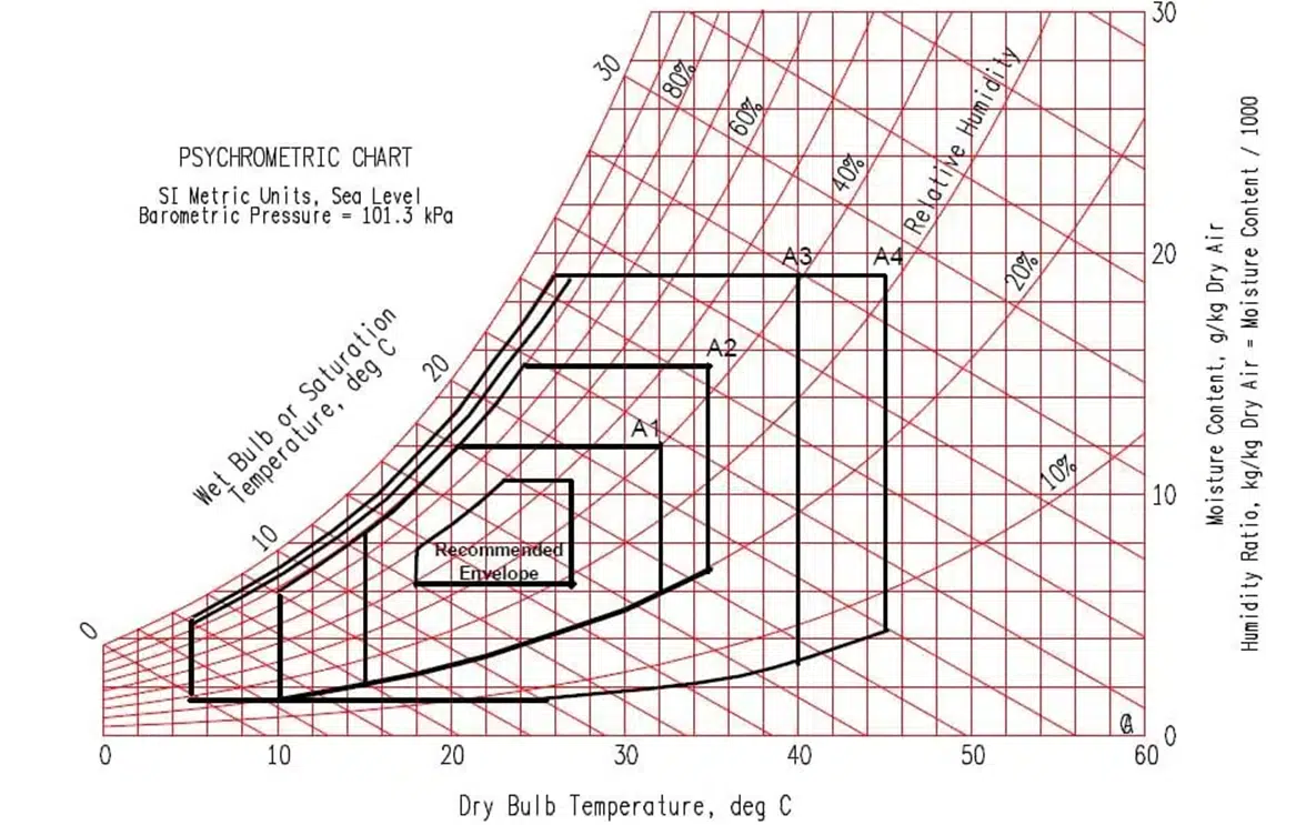
These recommendations may vary depending on the specifics of the equipment: continuous monitoring (sensors, management systems) is essential to quickly detect and correct any drift.
Cooling systems in the server room
Air conditioning with CRAC and CRAH units
CRAC units
- Work like domestic air conditioners: compressor + refrigerant.
- Hot air drawn in, cooled over a coil, redistributed.
- Self-contained, suited to loads < 200 kW.
CRAH units
- No compressor: fans + coils cooled by chilled water.
- Centralised cooling, more energy-efficient.
- Suited to loads > 200 kW.
CRAC units use a compressor and a refrigerant to cool the ambient air: the hot air is drawn in, cooled as it passes over a coil containing the refrigerant, then redistributed. They are generally self-contained and particularly suited to small to medium-sized data centers.
CRAH units are equipped with fans and coils cooled by chilled water from an external production system. More energy-efficient because they use centralised cooling, they are suited to larger data centers.
Raised floors and flow management
Using raised floors is a common practice to optimise air circulation. These floors are made up of modular tiles laid on a metal structure, creating a void — called a plenum — between the original floor and the raised floor, which acts as a duct for distributing the cooled air.
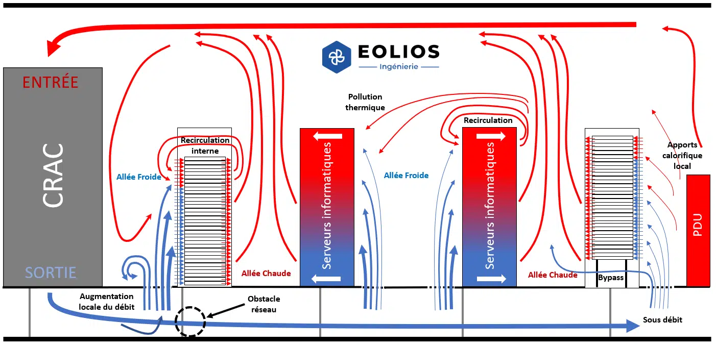
The cold air is channelled under the raised floor and distributed into the cold aisles through perforated tiles; the equipment draws in this cool air to cool its components, then discharges hot air into the hot aisles, which is then captured by the CRAC or CRAH units to be cooled again. This separation minimises the mixing of flows and improves energy efficiency.
Cooling circuits and heat dissipation
Chillers and chilled-water systems
Two complementary building blocks
- Chillers — thermodynamic devices producing chilled water (compression/expansion cycle). The water is cooled to between 6 °C and 12 °C, then sent to the CRAHs or heat exchangers; they can incorporate free cooling.
- Chilled-water systems — chilled water circulates through a pipe network to supply the CRAHs or in-row coolers (InRow) close to the racks; in a closed loop, the water returns to the chillers after absorbing the heat.
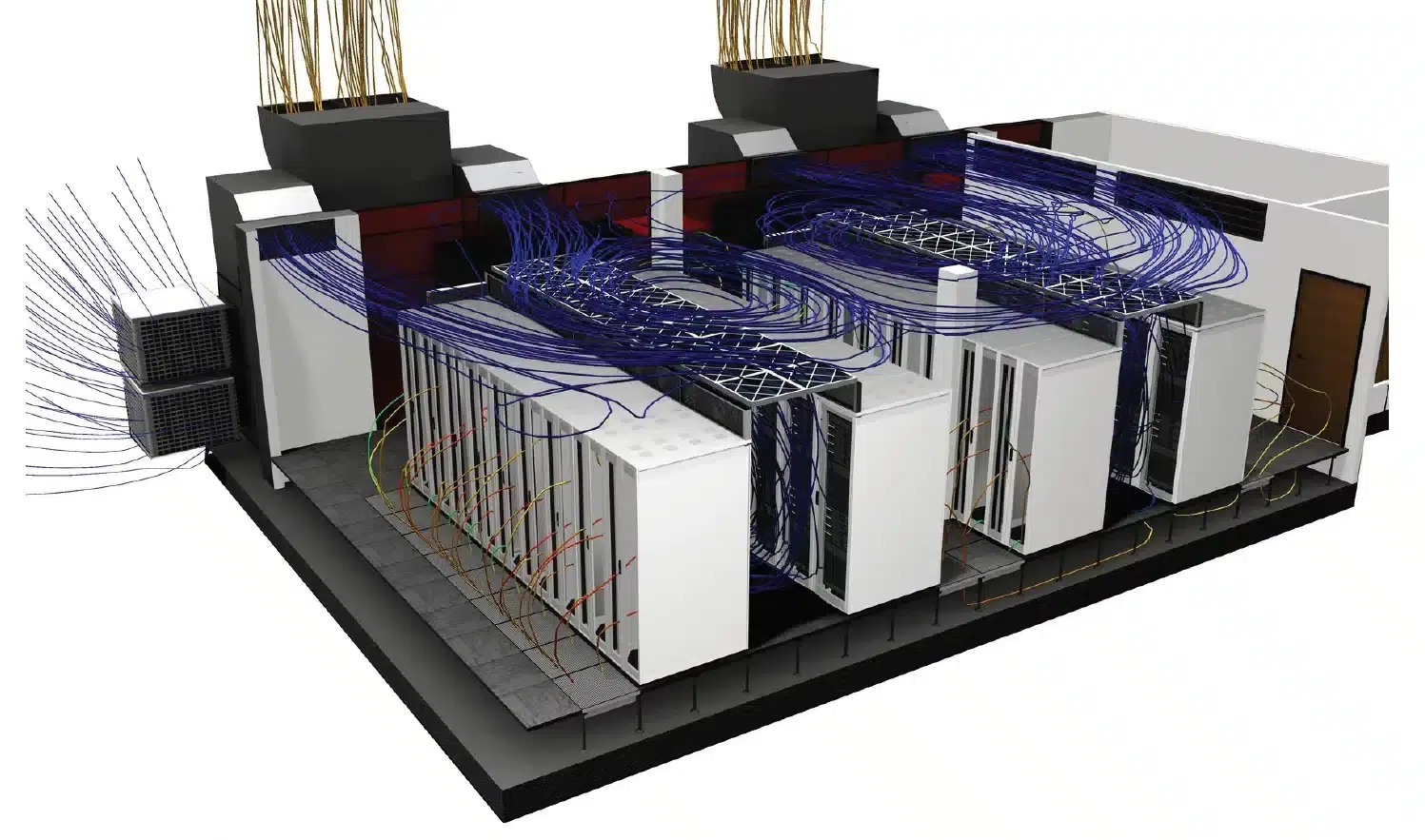
These conventional systems are essential to maintaining optimal thermal conditions; their choice depends on the size of the installation, the power density, budget constraints and energy-efficiency objectives.
Free cooling: outside air and heat exchangers
Free cooling exploits the outdoor climate to cool, reducing dependence on mechanical systems. Two implementations:
Direct free cooling
- Cool outside air is filtered and injected directly into the room; effective below ~25 °C, but requires monitoring of air quality and humidity.
Indirect free cooling
- Outside air cools an intermediate fluid via a heat exchanger; better control of humidity and air quality.
The effectiveness of free cooling depends heavily on local climate conditions: decisive in regions with cold winters, more limited in hot climates.
Adiabatic cooling and evaporation
Adiabatic cooling relies on the evaporation of water, which absorbs heat from the ambient air and lowers its temperature (humidification of the incoming air or adiabatic exchangers). Particularly effective in dry climates, it reduces dependence on chillers, lowers energy consumption and improves the PUE.
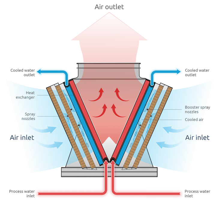
Its main challenge is humidity management: an excess can lead to condensation and corrosion, hence the need for precise humidity control. Another aspect is water consumption, sometimes significant, raising environmental and regulatory questions (notably ICPE and cooling-tower (TAR) risk) — making it suitable only under certain well-controlled conditions.
Advanced solutions and innovations
Hybrid cooling: combining air / water
Hybrid cooling systems combine the advantages of free cooling and mechanical systems to optimise energy efficiency. A hybrid system can use free cooling when outdoor conditions are favourable and switch to mechanical cooling when the outside temperature rises: this flexibility reduces consumption while ensuring a stable temperature.
Another example is the use of adiabatic coolers combined with mechanical units: the air is first cooled by evaporation, then a mechanical system adjusts the temperature. This approach reduces the load on the mechanical systems, extending their lifespan and lowering operating costs.
Liquid cooling: immersion and direct contact
As power density increases, air cooling reaches its limits. Liquid cooling offers an alternative by using fluids to absorb heat directly from the components. Two main methods:
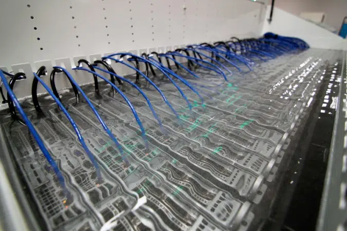
Immersion cooling
- The servers are immersed in a non-conductive dielectric liquid that absorbs the heat, then dissipated via heat exchangers. Eliminates fans, reduces noise and consumption, and allows higher power density.
Direct-contact cooling (direct-to-chip)
- Cold plates are installed directly on the critical components (processors); a fluid circulates through them, absorbing the heat and carrying it to a heat exchanger. Precise temperature control, integrable with minimal modifications.
Liquid cooling offers significant advantages in thermal efficiency and reduced consumption. However, it requires higher investment, specialised maintenance, and the leak risks and sealing must be carefully managed.
On-chip cooling and emerging technologies
On-chip cooling (direct-to-chip) integrates microchannels directly into the chips or processor modules: a fluid circulates through them, absorbing the heat at the source. This method offers extremely efficient dissipation, essential for intensive computing or servers dedicated to artificial intelligence.
Emerging technologies include two-phase systems (the fluid changes state as it absorbs heat, offering greater capacity) as well as research into phase-change materials and nanofluids.
Comparative analysis of cooling methods
Choosing the best method
The energy efficiency and environmental impact of data centers depend largely on the cooling systems used. They are analysed against several criteria: PUE, energy consumption, ecological footprint, technical constraints, costs — but also safety.
A word of caution on safety
Safety is a fundamental criterion: any breakdown, overheating or failure can cause costly service interruptions and jeopardise data integrity. The choice of cooling system must ensure equipment reliability and limit the risk of thermal malfunctions.
One of the major risks is component overheating, which can lead to premature degradation and unexpected shutdowns — even irreversibly damaging processors or storage units. To avoid these incidents, systems must be designed with redundancy mechanisms that activate a backup circuit in the event of a failure.
Learn more: fire simulations in data centersBesides thermal management, the risks of liquid leaks must be taken into account, particularly for liquid cooling: introducing a heat-transfer fluid close to electronic components requires rigorous monitoring, leak sensors and containment systems.
Risk comparison — air-based methods, although less energy-efficient, present a lower risk: no direct exposure to liquids, fewer mechanical accidents; but they require regular maintenance of filters and ventilation. Technologies such as adiabatic cooling and free cooling must be assessed for their impact on overall safety (condensation from humidity, outside-air quality).
Energy-performance criteria
Power Usage Effectiveness (PUE) is the main indicator: it is calculated by dividing the data center's total consumption by that of the IT equipment alone. A PUE of 1.0 indicates optimal efficiency; in France, the average PUE is 1.36.
Influence on PUE
- Air cooling — higher PUE (energy-hungry air conditioners, fans).
- Liquid cooling — more efficient dissipation; can improve PUE by more than 15%.
- Free cooling — considerably reduces cooling-related consumption, improving PUE.
Environmental impact
Three levers
- Energy consumption — air is energy-hungry (high carbon footprint); liquid and free cooling consume less.
- Water consumption — adiabatic cooling uses water, problematic in regions where the resource is limited.
- Heat recycling — recovering heat to warm adjacent buildings improves overall efficiency.
Technical constraints and limits
Each method has advantages but also constraints. The choice depends on the data center configuration, local climate conditions, installation and operating costs, and energy-efficiency requirements.
Air cooling — a proven, reliable and accessible solution with moderate installation costs (ideal for small and medium infrastructures); but its thermal efficiency is reduced at high density, leading to higher consumption and carbon footprint.
Liquid cooling — optimal thermal efficiency for high-density infrastructures, reduces consumption, and the residual heat can feed a district-heating network; but high installation cost, complex maintenance and leak risks to manage.
Free cooling — reduces consumption by exploiting outside air, improves PUE; but depends closely on the site's climate and requires advanced filtration systems.
Adiabatic cooling — combines energy efficiency and cost reduction, especially in a dry environment; but relies on water (water-resource management) and loses efficiency when humidity is too high.
| Method | Thermal efficiency | Installation cost | Maintenance | Environmental impact | Main limitation |
|---|---|---|---|---|---|
| Air (CRAC / CRAH) | Moderate — reduced at high density | Moderate | Simple — filters & ventilation | High — energy-hungry | Poorly suited to high densities |
| Liquid (immersion / direct-to-chip) | Optimal — high densities | High | Complex — fluids & sealing | Reduced — recoverable heat | Leak risk to manage |
| Free cooling | High — depending on climate | Moderate to high | Advanced filtration required | Low | Depends on local climate |
| Adiabatic | High — in dry climates | Moderate | Humidity control | Water — consumption to watch | Loses efficiency if the air is humid |
In short, each method offers a balance between performance, costs and operational constraints. The choice of the optimal solution depends on the specific needs of the data center, the environmental conditions and the sustainability objectives.
Optimising cooling with EOLIOS
A global approach
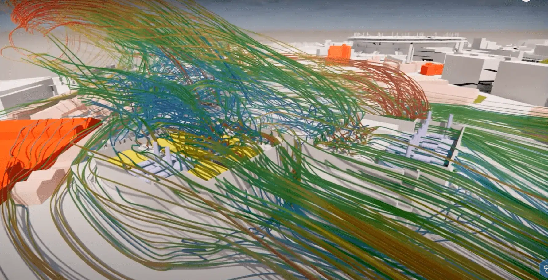
Optimising cooling systems is a key challenge for modern data centers: energy efficiency and thermal management directly affect operating costs, sustainability and environmental impact. EOLIOS supports players in the sector through an integrated approach based on CFD simulation, to analyse and optimise heat dissipation in the room and heat removal to the outside.
Learn more: what is CFD simulation?Reducing consumption by optimising thermal flows
Poor airflow management creates overheating zones (hot spots) and excessive consumption. EOLIOS carries out internal CFD studies to map air circulation and identify inefficiencies. Several actions follow:
Levers for action
- Optimisation of hot and cold aisles to limit hot-air recirculation.
- Improvement of the layout of CRAC and CRAH units according to actual needs.
- Identification of hot spots and recommendations to mitigate them.
- Integration of air-containment solutions (separators, perforated floors).
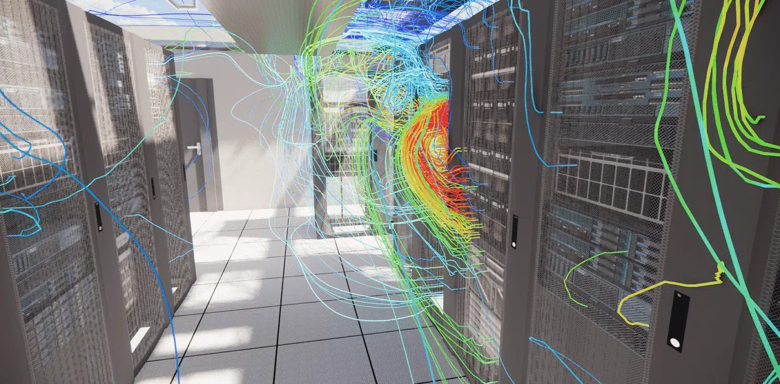
These actions significantly reduce the consumption of the air-conditioning systems, maximising cooling efficiency while limiting the thermal overload of the IT equipment.
Internal heat dissipation via CFD
EOLIOS carries out internal CFD simulations to visualise the heat flows and thermal gradients in the room, and optimise several aspects:
Optimisations
- Reduction of hot-air recirculation phenomena.
- Validation and optimisation of the systems by virtually testing different scenarios.
- Improved performance of the air-handling units for more even dissipation.
Dissipation to the outside and environmental impact
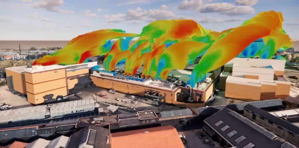
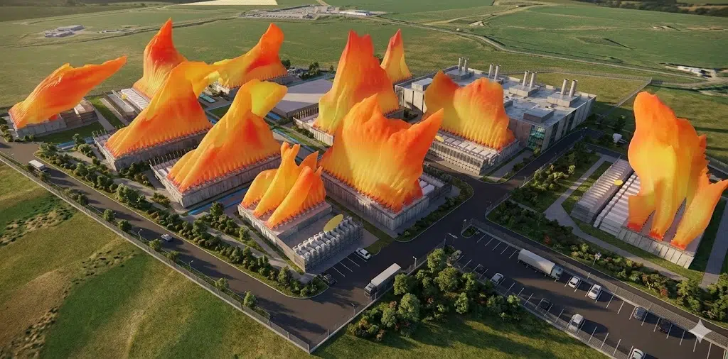
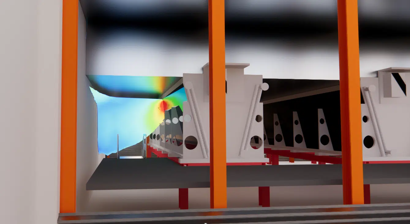
Once the heat is extracted from the equipment, it must be efficiently dissipated to the outside. EOLIOS carries out external CFD simulations taking several factors into account:
Factors studied
- Study of thermal discharges to avoid heat build-up around the buildings.
- Optimisation of the location of the heat exchangers and chillers.
- Analysis of external airflows to minimise recirculation and maximise free cooling.
Securing infrastructures through thermal management
Beyond energy efficiency, thermal safety is a major issue. EOLIOS integrates it as a key parameter of its CFD studies to anticipate and prevent risks:
Predictive vision
- Identify the potential points of failure related to temperature variations.
- Assess the impacts of a malfunction to size the redundancy.
- Optimise flow management in the event of a partial failure, to avoid a rapid temperature rise.
Towards more efficient and sustainable data centers
By combining energy analysis, internal and external CFD simulation, and safety optimisation, EOLIOS helps to reduce consumption and improve PUE, optimise equipment layout, limit the environmental impact of thermal discharges and strengthen the safety of the installations. Thermal optimisation thus becomes a lever for efficiency and performance.
Internal and external CFD studies, PUE, free cooling, thermal safety: our engineers optimise your cooling.