Recommendations for optimal ventilation and effective pollutant dispersion in a steelworks: sizing and location of a new static roof aerator.
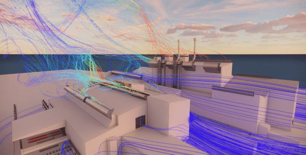
The project carried out by EOLIOS for the Aubert & Duval steelworks consists of a study of the sizing and location of a new static aerator (Robertson) on the roof. The main objective of this study is to ensure effective ventilation of the steelworks by determining the optimal dimensions of the static aerator.
The essentials. EOLIOS sized and positioned a new static aerator (Robertson) on the roof of the Aubert & Duval steelworks. Surveys of the three halls, smoke tests, infrared thermography and twelve months of weather data fed a CFD model: adding a ridge ventilator above furnace 8 brings the temperature under the roof down and speeds up smoke evacuation, at a nearly constant extraction flow rate.
EOLIOS is carrying out a project for the Aubert & Duval steelworks, consisting of a study of the sizing and location of a new static aerator on the roof. The main objective is to ensure effective ventilation of the steelworks by determining the optimal dimensions of the aerator. This will make it possible to comply with the pollutant-emission standards, to optimise aeraulic and thermal comfort, and to improve air quality.
The study also includes an in-depth analysis of the air movements in the steelworks in order to better understand the distribution of the dust and smoke generated by the industrial operations. This analysis will make it possible to assess the impact of the aerator on the dispersion of these particles and to propose pollution-prevention and control measures.
The results of this study will be essential to precisely define the dimensions of the aerator and its optimal location on the roof. In addition, they will make it possible to formulate recommendations to limit the dispersion of the dust and smoke, thereby ensuring better air quality and reducing the risks of pollution.
A static aerator (or roof ventilator, Robertson type) is a motorless roof-extraction device: it discharges hot air by thermal draught, the density difference between the warm indoor air and the outdoor air driving the upward movement.
It should be noted that the study takes into account several different scenarios, with different configurations and air flow rates. The objectives of the study are therefore to size the aerator appropriately for each scenario, while complying with the emission standards and improving air quality.
During the study carried out for the Aubert & Duval steelworks, several activities were undertaken to understand the thermo-aeraulic phenomena of the site.
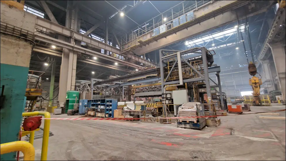
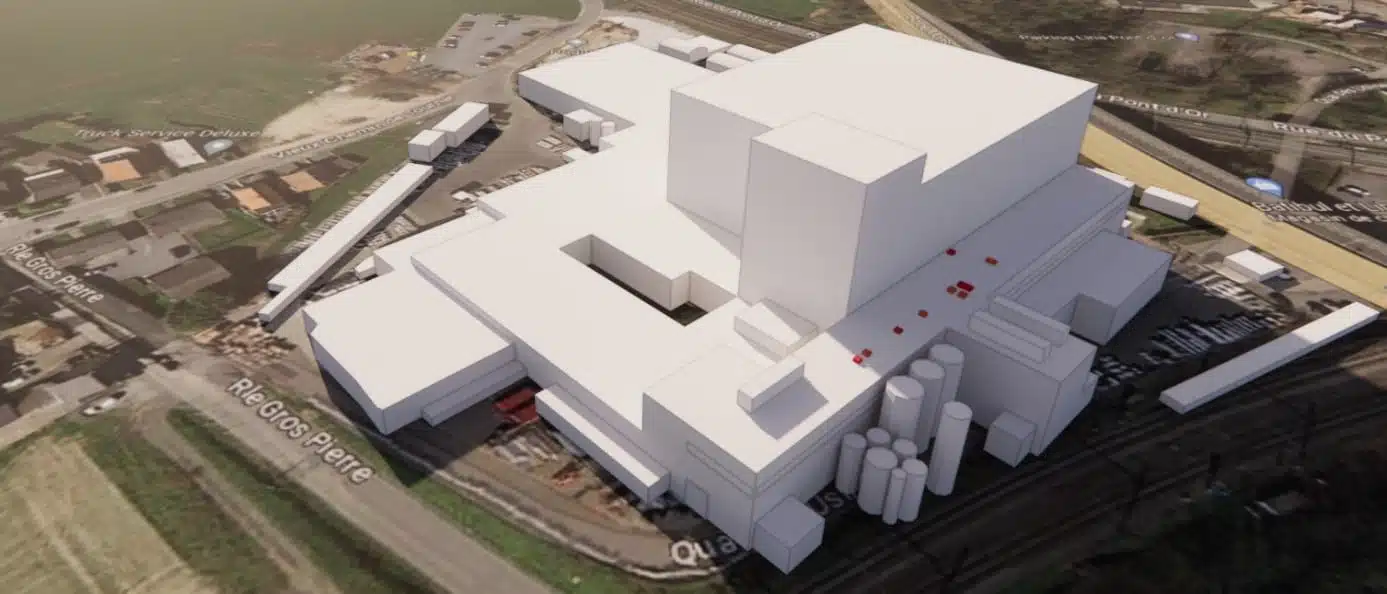
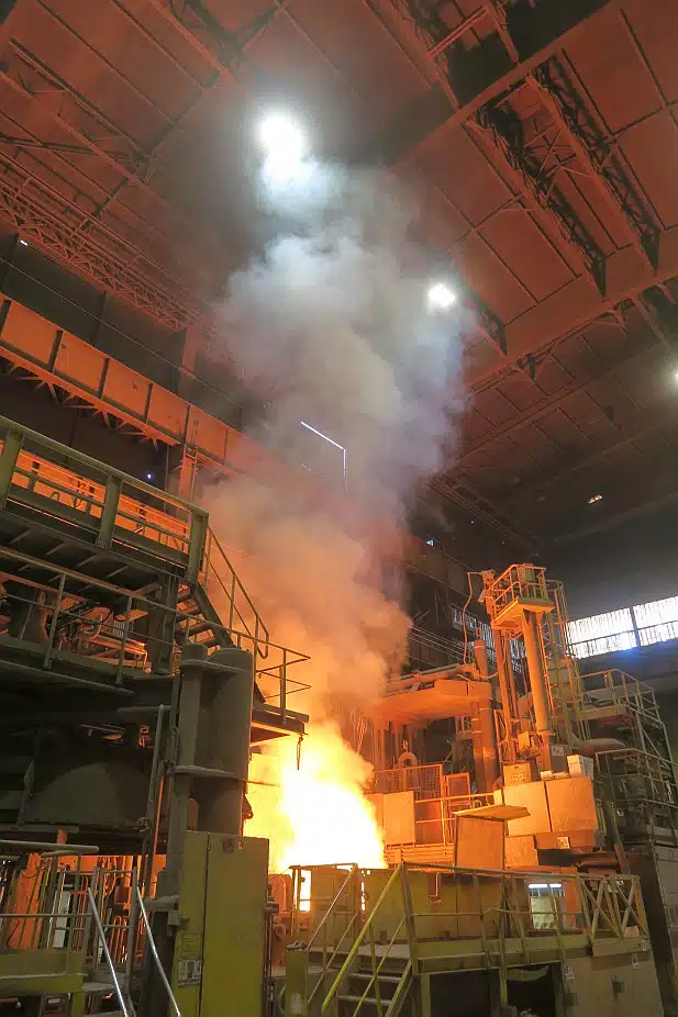
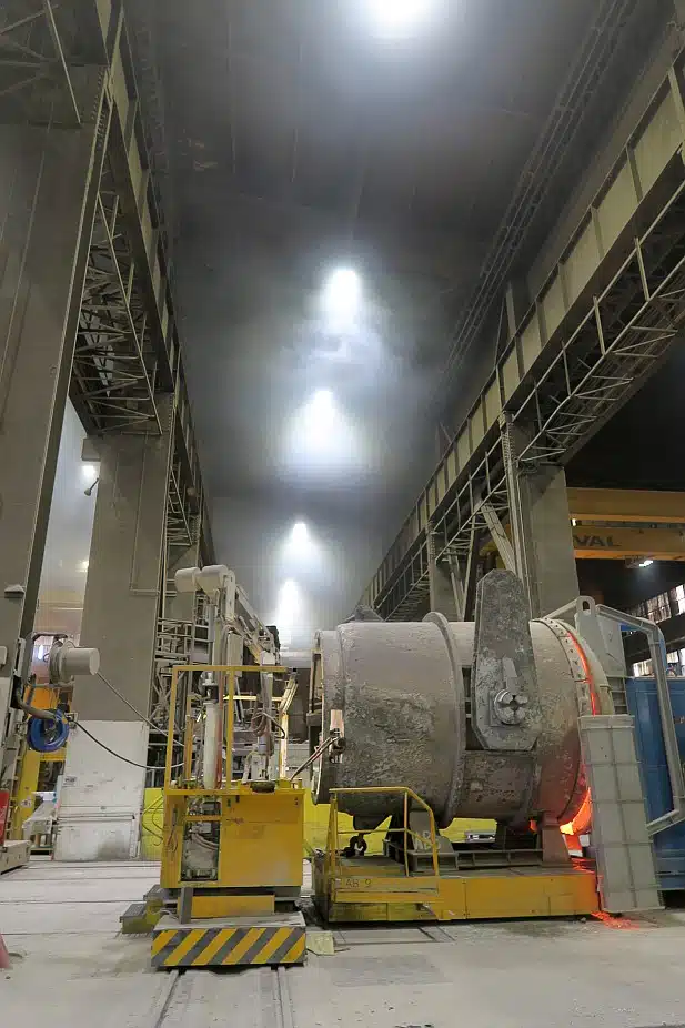
A full tour of the plant made it possible to visualise the various processes and to understand the specific issues.
Measurements were taken to determine the location and dimensions of the louvres and openings in the three halls of the steelworks.
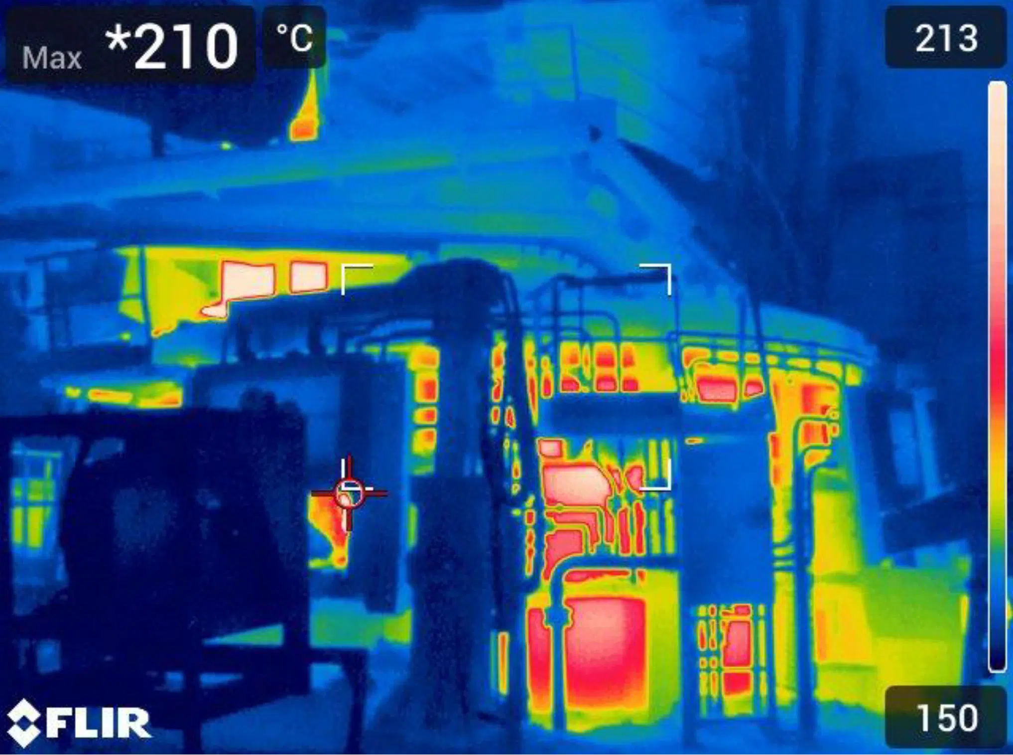
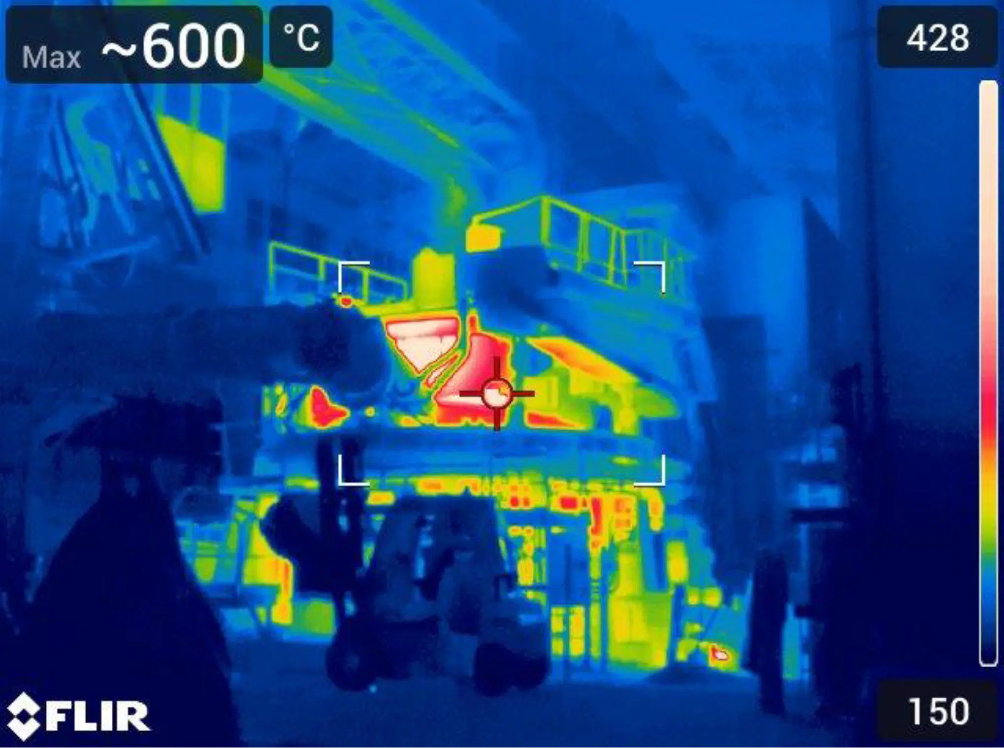
Thermal images were taken to measure the wall temperatures, while dimensional measurements were made to build 3D models of the missing parts.
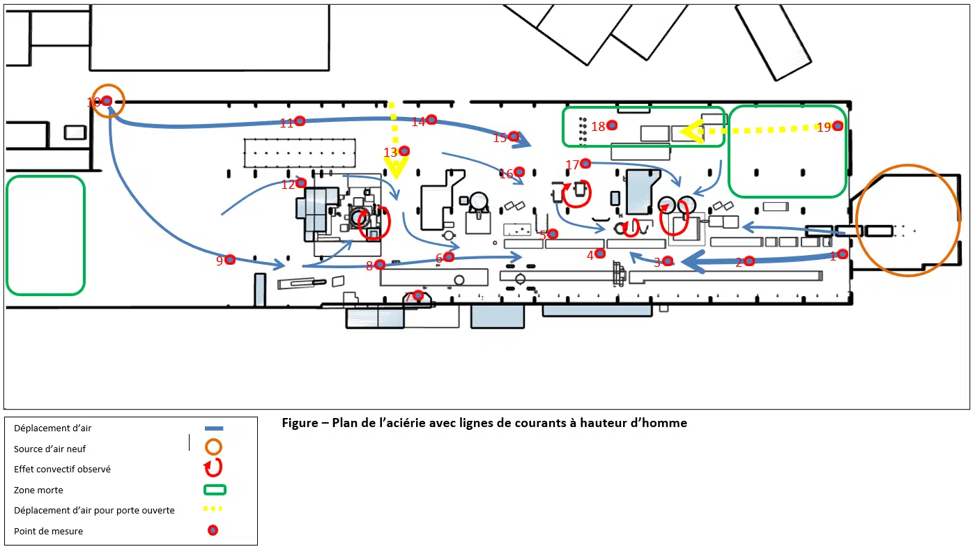
Smoke tests have become an essential tool for assessing thermo-aeraulic phenomena on industrial sites. Indeed, these tests make it possible to visualise the airflows and to identify any stagnation zones, thus providing a precise analysis of the air circulation in a given environment.
A smoke test consists of releasing a non-polluting tracer smoke, based on water and glycol, to make the air trajectories visible. It reveals the stagnation zones and the real circulations, impossible to perceive with the naked eye.
These smoke tests play a key role in the analysis of the site's thermo-aeraulic phenomena. They make it possible to identify the sensitive points and to propose suitable solutions to improve the air circulation and the quality of the thermal environment.
Recently carried out on the industrial site, these tests made it possible to highlight the various air trajectories, from the heat source to the ventilation outlets, passing through all the elements of the building. Thanks to these observations, the engineers were able to determine the hot spots as well as the areas where the air was poorly ventilated.
To carry out these tests, special smoke was used. It was generated from a non-polluting water- and glycol-based liquid, thus ensuring harmlessness to the environment and to the health of the people present on the site.
The results obtained made it possible to detect areas where the air was stagnant, thereby promoting the formation of hot air currents and microclimates unpleasant for the workers.
Thanks to this information, improvements could be made to the site's ventilation, thereby making it possible to create a more pleasant and safer working environment.
Next, thermal images were used to highlight the main sources of the thermal phenomena and the various areas that are more or less dense in heat.
The recorded temperatures were compared with the CFD simulation results to verify their consistency. The emissivity of the various surfaces was taken into account to estimate the temperatures.
During two site visits, the outdoor weather conditions were recorded, which will serve as a basis for the baseline simulations. Then, the weather data from the weather station closest to the site were collected over a 12-month period.
This precise information on the weather readings will allow us to select the appropriate climate conditions according to the study's objectives. The conditions recorded during the second visit were used for the first modelling in order to confirm a correct implementation of the conditions in the model.

The information collected includes the wind speed and direction, as well as the average minimum temperature in winter and the average maximum temperature in summer. In addition, the most extreme recorded temperature peaks are also taken into account.
These data play a crucial role in adapting the ventilation strategies to guarantee the optimal comfort of the plant operators throughout the year.
The simulation was carried out using the CFD (Computational Fluid Dynamics) method, which makes it possible to analyse and predict the movements of fluids such as air and gases. This virtual approach makes it possible to simulate the thermo-aeraulic phenomena in the steelworks, taking into account the interactions between the various surfaces, the heat sources and the airflows. Thanks to CFD, it is possible to visualise and analyse in detail the flows, the temperatures and the gas concentrations, which contributes to a better understanding of the processes and to the optimisation of the performance and safety of the facilities.
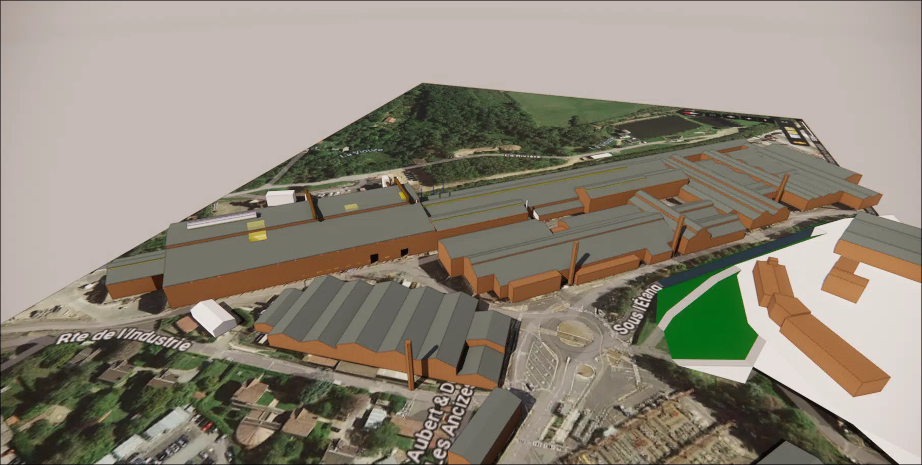
Geometric modelling is a key step in CFD simulations. It makes it possible to faithfully represent the geometry of the site or building studied and to define the boundary conditions such as the walls, the openings to the outside, and the internal heat inputs. Geometric modelling also makes it possible to simplify the model by removing the elements that are not relevant, thus facilitating the interpretation of the results.
The simulation was carried out using the CFD (Computational Fluid Dynamics) method, which makes it possible to analyse and predict the movements of fluids such as air and gases. This virtual approach makes it possible to simulate the thermo-aeraulic phenomena in the steelworks, taking into account the interactions between the various surfaces, the heat sources and the airflows. Thanks to CFD, it is possible to visualise and analyse in detail the flows, the temperatures and the gas concentrations, which contributes to a better understanding of the processes and to the optimisation of the performance and safety of the facilities.
In the context of buildings, CFD makes it possible to study the air velocities, the pressures and the temperatures inside and around built spaces. This makes it possible to better understand the aeraulic and thermal conditions, notably for the design of ventilation and air-conditioning systems. CFD simulations are particularly useful for improving indoor comfort by optimising the airflows, which contributes to better energy efficiency and to occupant well-being.
During this study, two configurations were examined to assess the effectiveness of dust extraction in the case of the furnace in open-door mode. The first configuration was the baseline configuration, while the second configuration included the addition of static aerators and the closure of the inappropriate louvre.
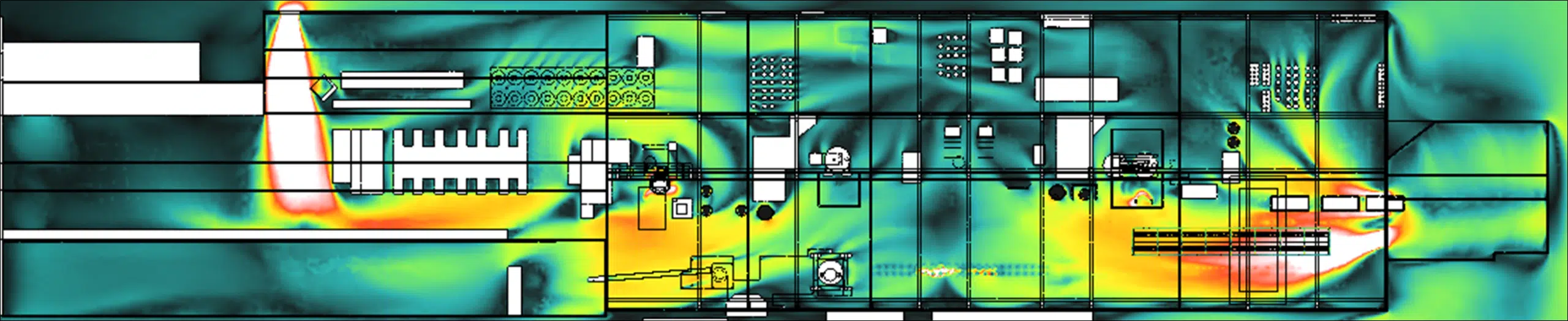
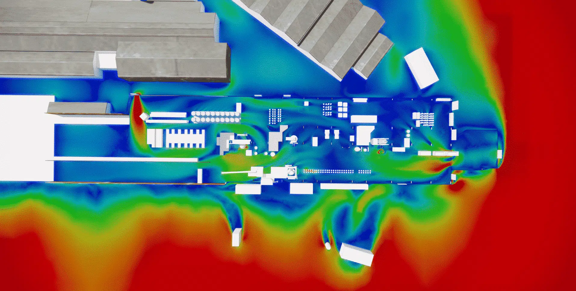
The results showed that in the second situation, a much greater dust extraction than in the baseline configuration was observed, allowing a faster discharge closer to the emission source. This helps ensure a cleaner and safer working environment.
One of the main challenges of this study is to understand how heat is distributed inside the plant and how it affects the various work areas. It is necessary to identify the areas where temperatures can be excessively high and to put in place measures to mitigate the impact of heat on the employees.
The study of the plant's initial configuration showed poor air circulation in some areas, which led to high temperatures in them. This can be due to factors such as the location of the heat sources, the layout of the equipment or the air circulation in the space. The addition of static aerators in the second configuration made it possible to remedy this problem.
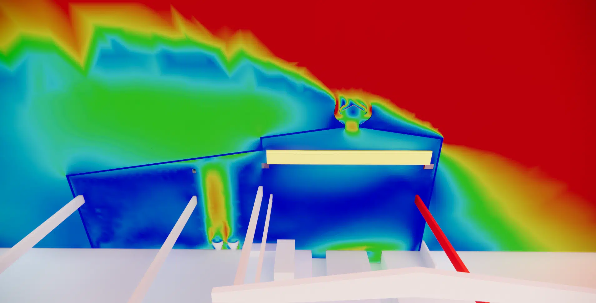
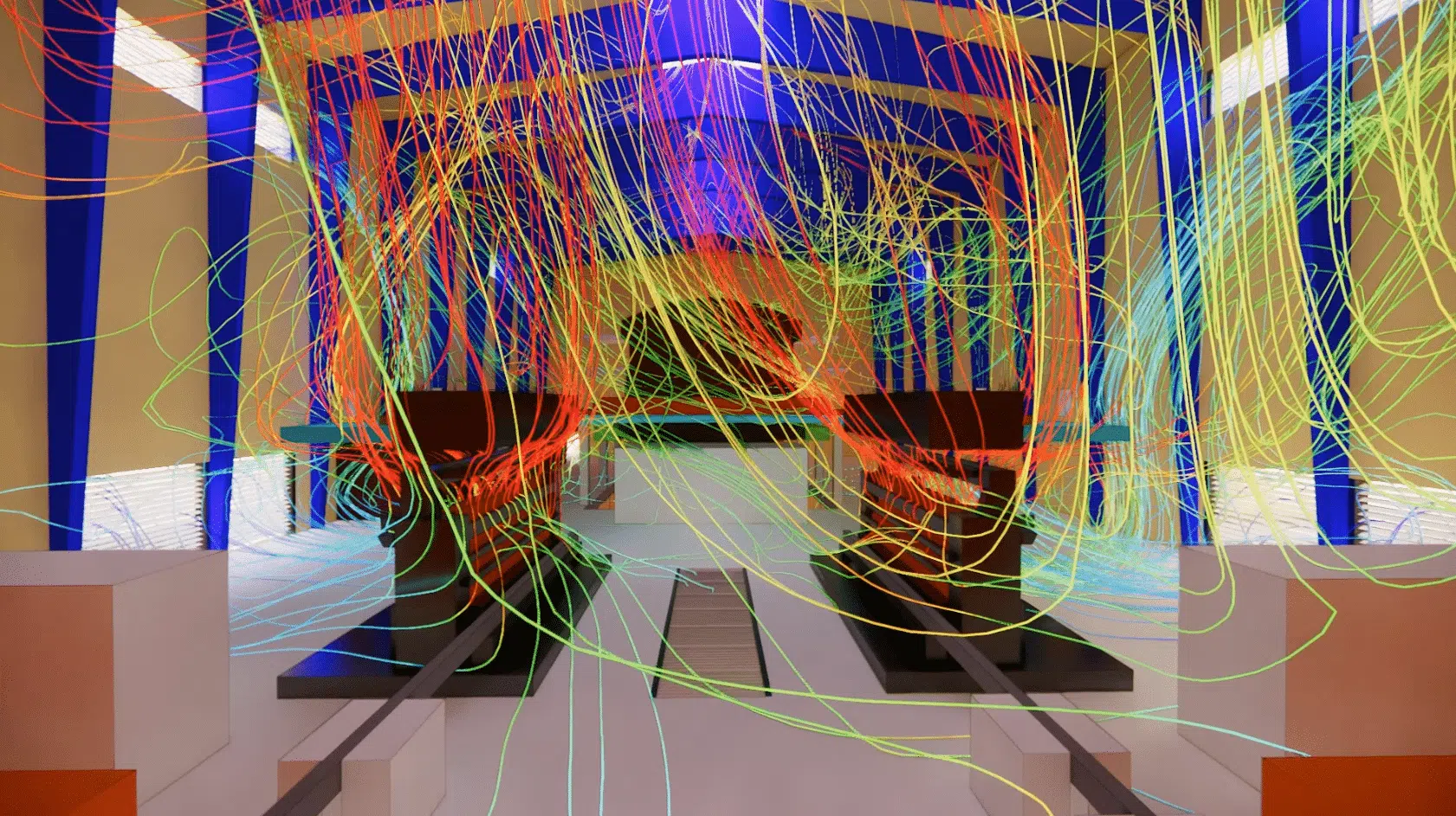
These aerators helped to increase the air circulation through the plant by facilitating the discharge of hot air and promoting the entry of fresh air. This had two beneficial effects. First, the homogenisation of the air velocities made it possible to reduce the low-circulation areas, which contributed to a better distribution of heat in the plant. This led to a reduction in the temperature ranges between the various work areas, thereby improving the thermal comfort of the employees. In addition, the homogenisation of the temperatures made it possible to reduce the high temperatures, particularly in summer conditions, where the outdoor temperatures can be higher.
The study of the distribution of dusts and pollutants in the plant highlighted the effectiveness of the extraction systems such as the static aerators and the hoods. These devices aim to reduce the presence of dusts and pollutants in the plant air. The plant's first configuration showed high concentrations of dusts and pollutants mainly located near the furnaces. However, across the rest of the plant, the dust and pollutant concentrations were relatively uniform.
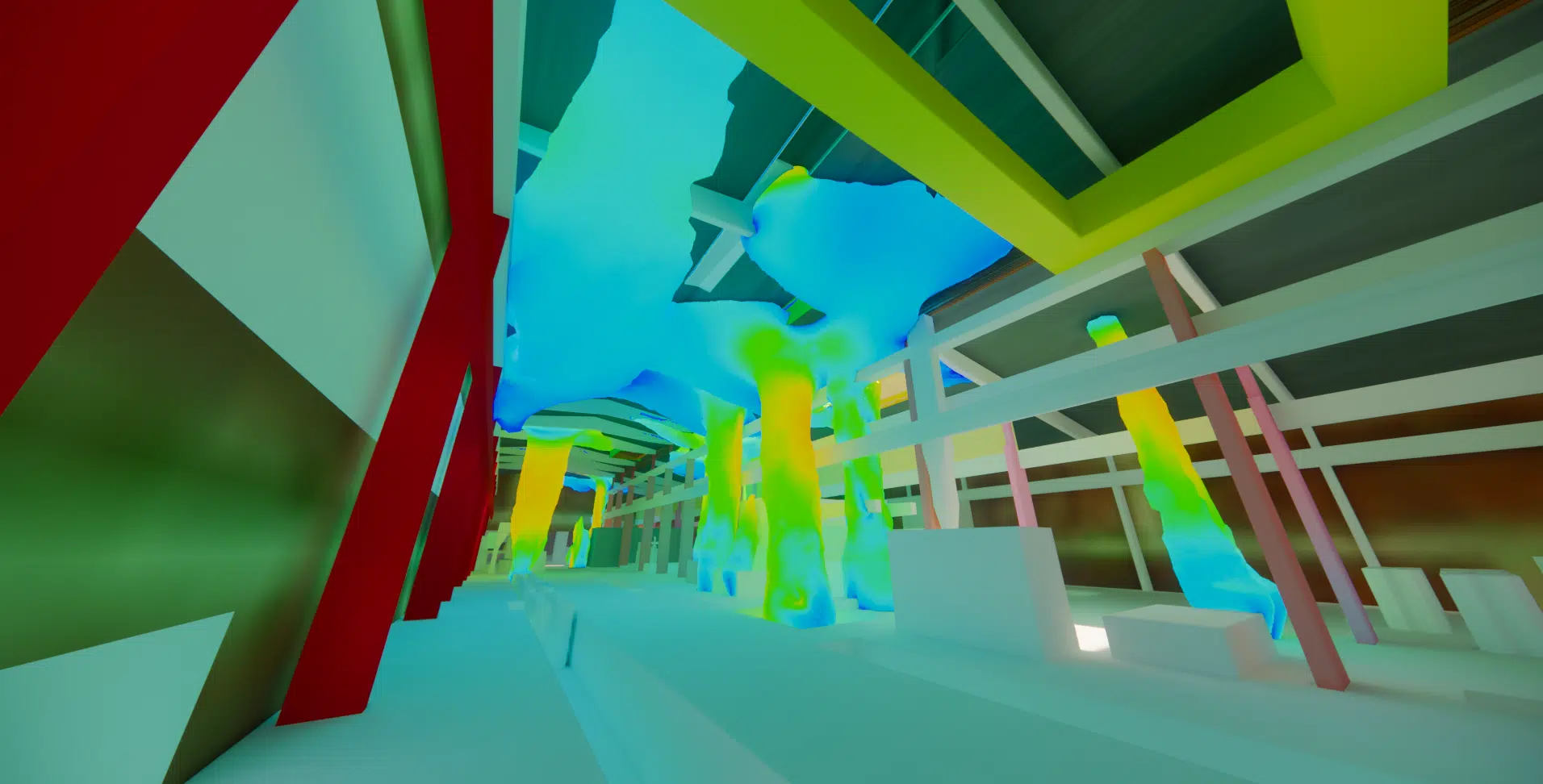
The second configuration, for its part, made it possible to improve the dispersion of the air movements in the lower part of the plant, thereby reducing the zones of high dust and pollutant concentrations. This suggests that the optimisation of the extraction systems contributed to a better distribution of the particles and pollutants throughout the plant, allowing easier discharge. These results highlight the importance of an appropriate design of the extraction and ventilation systems in plants. By identifying the main sources of dusts and pollutants, it is possible to put in place effective collection and extraction devices to reduce their dispersion in the plant air.
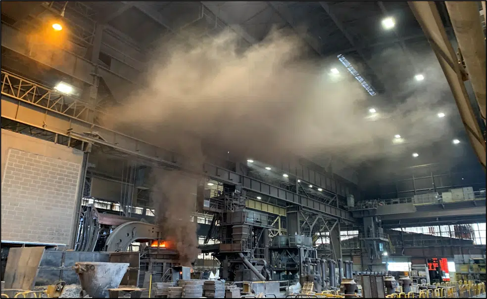
The neutral pressure plane is the height, in a naturally ventilated space, where the indoor pressure equals the outdoor pressure. Below it, air enters; above it, air leaves. Its position guides the placement of the air inlets and outlets.
Neutral pressure planes play a crucial role in the design of the natural-ventilation systems of buildings. They are used to determine the strategic locations where the air inlet and outlet openings should be placed in order to optimise the air circulation. A neutral pressure plane is an imaginary surface inside the ventilated space where the static pressure is balanced. This means that the forces exerted by the incoming and outgoing air in this zone are equal. In most cases, the air inlet openings are placed at the bottom of the ventilated space, where the pressure is higher.
The higher pressure is generally due to temperature differences between the inside and outside of the building, as well as to the air density. These inlet openings allow fresh air to enter the ventilated space. On the other hand, the air outlet openings are placed at the top, where the pressure is lower. This is attributed to the height difference between the inlet and outlet openings, as well as to the air currents created by external factors such as the wind.
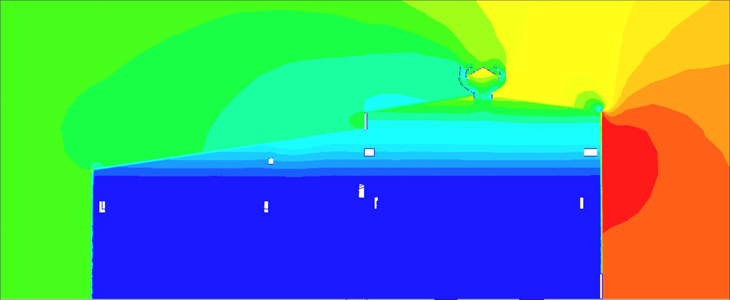
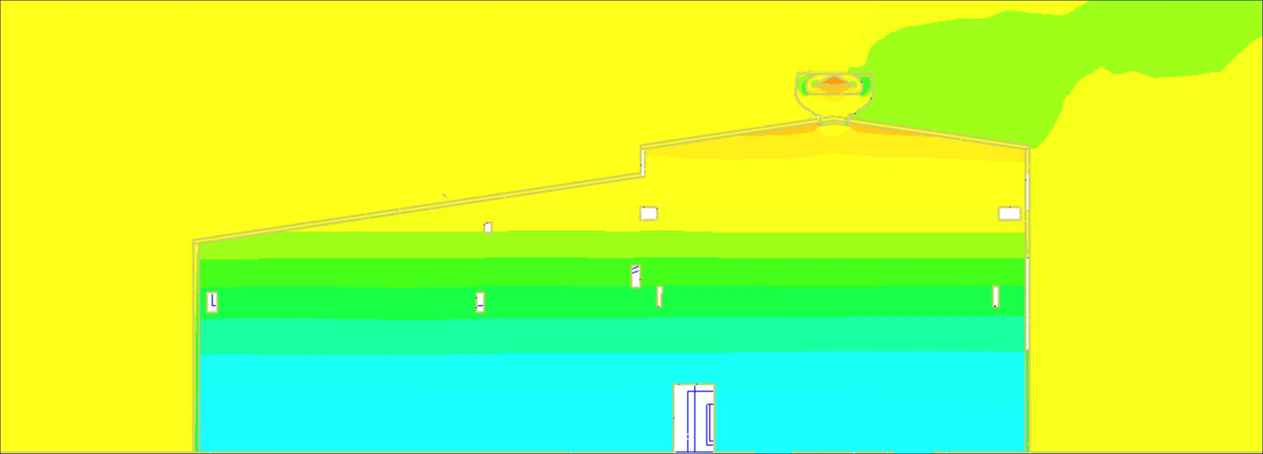
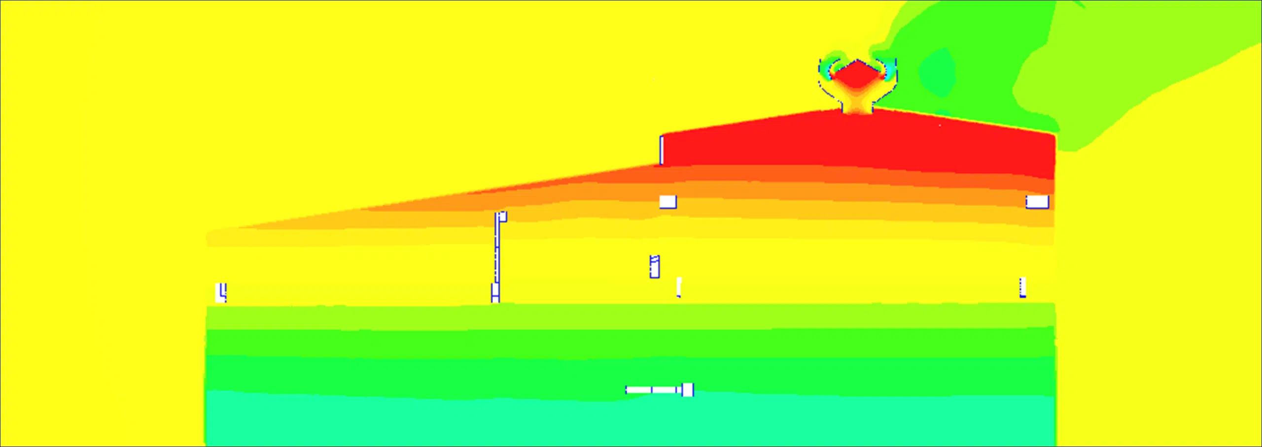
By positioning the outlet openings at the top of the ventilated space, stale air is discharged more efficiently, thereby ensuring better indoor air quality. By respecting the neutral pressure planes, designers can ensure effective natural ventilation and a uniform distribution of fresh air throughout the space.
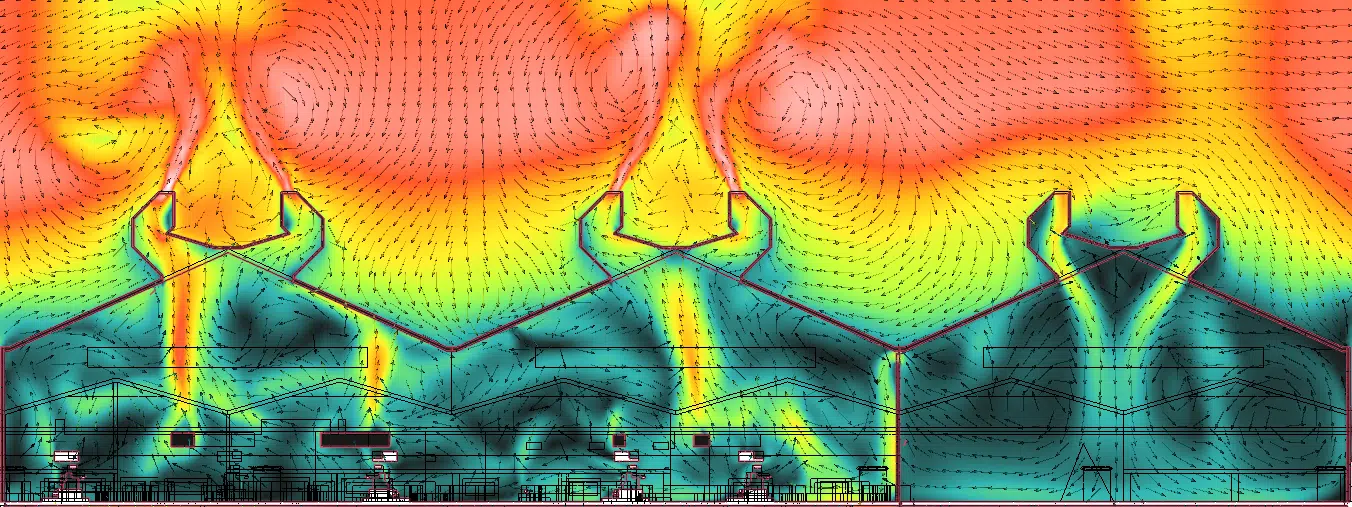
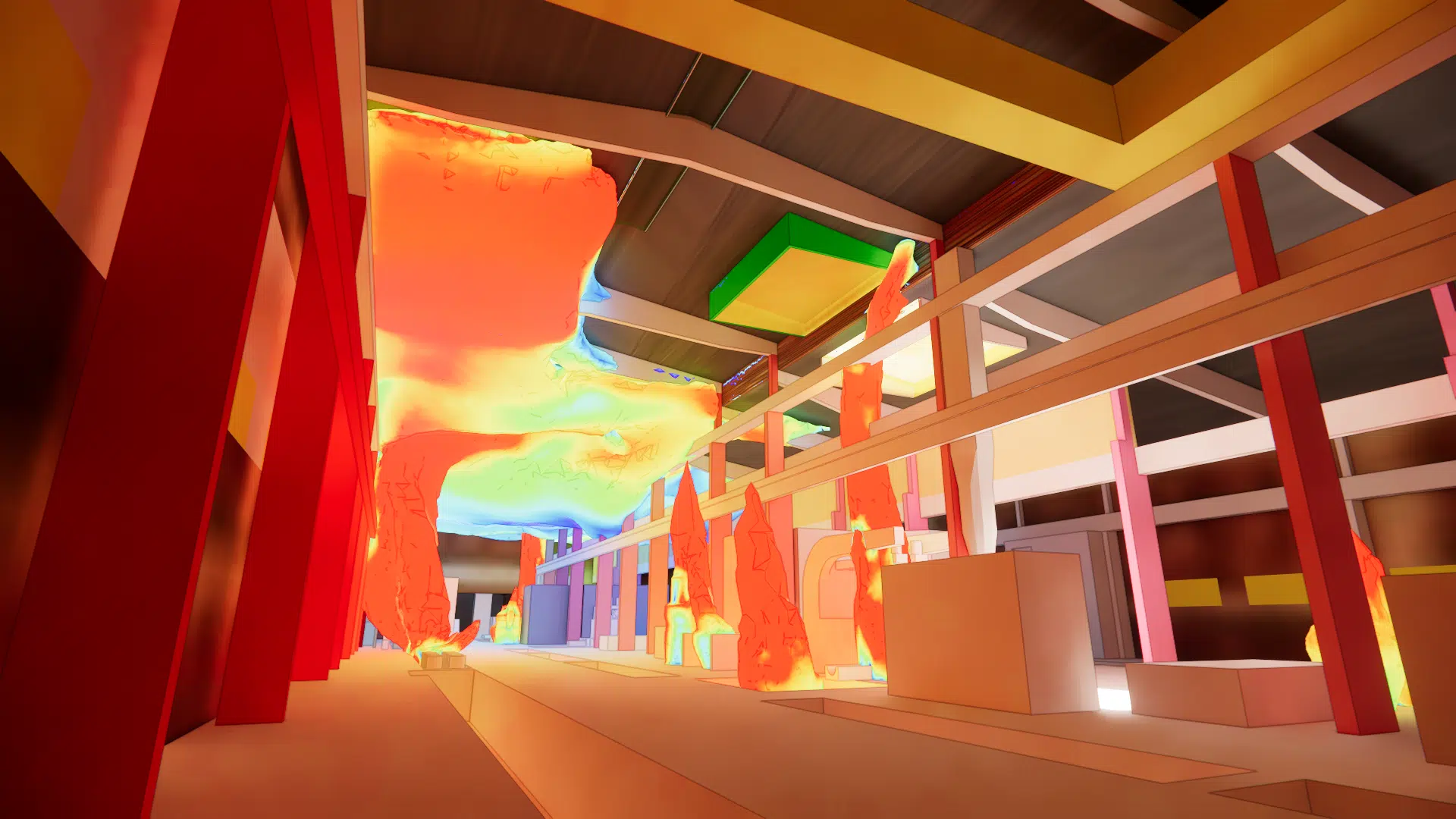
This step is part of the sizing of static aerators by CFD. The simulations carried out then included the installation of a new ridge ventilator above furnace 8. The simulation results showed that the newly added ridge ventilator had a significant impact on the airflows. A disappearance of the directed flow from furnace 8 towards the small ridge ventilators already present is observed.
Regarding the temperature distribution, the results indicate a distribution similar to that of the previous scenarios, but with a clear drop in temperature under the roof thanks to the presence of the ridge ventilator.
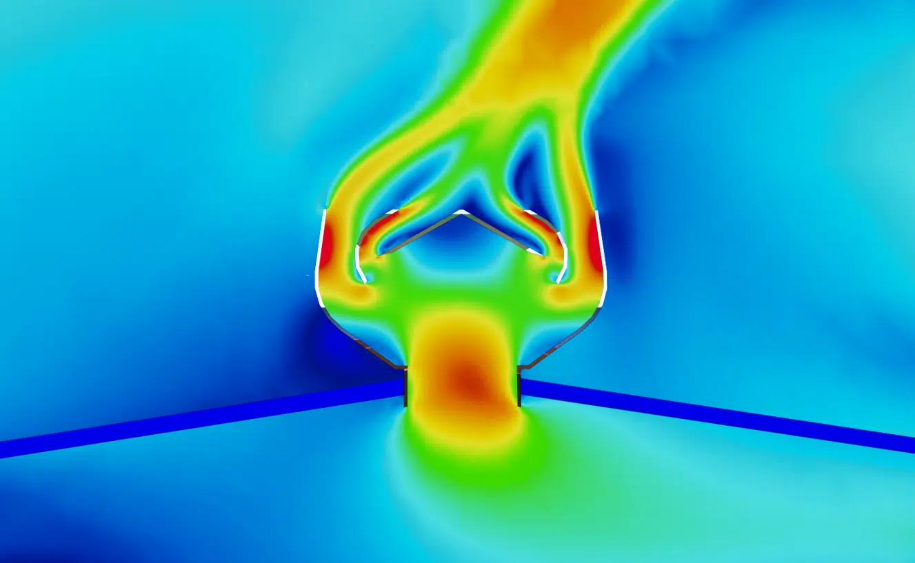
The temperature under the roof drops considerably thanks to the rapid discharge of the hot air laden with heat by the ridge ventilator. The results also highlight that the total extraction flow rate remains broadly constant, with a slight increase compared with the existing configuration. These results demonstrate the effectiveness of the ridge ventilator added above furnace 8 in rapidly discharging the heat-laden hot air. This modification therefore helps to improve the airflows and the thermal conditions in the building.
The objective of the study was to size and position the new static ventilation device on the roof of the steelworks. It also sought to map the air movements and the temperature distribution throughout the steelworks, as well as to analyse the dust/smoke distribution at the aerator.
The velocity plans at head height showed a relatively uniform distribution, independent of the outdoor conditions. The convective movement caused by the hot elements such as the furnaces, the cast ingots, the slag bins and the ladles is the main aeraulic driver of the steelworks.
At the static aerator (Robertson), the velocity patterns demonstrated effective discharge along its entire length, with a relatively uniform distribution.
The distribution of the pollutants in the static-aerator section revealed a zone of high concentration slightly offset towards the furnace, while the rest of the Robertson showed a uniform distribution, independent of its geometry.
The study carried out by EOLIOS made it possible to obtain valuable recommendations for sizing and optimising the steelworks' static-ventilation device. These recommendations will ensure better ventilation, effective dust/smoke dispersion and an overall improvement of the climate in the premises. This will help improve employee comfort, keep the facilities in optimal conditions and comply with the environmental standards in force.
Key takeaway. The natural ventilation of a steelworks relies on the convective driver of the hot sources (furnaces, ladles, slag bins). Well sized and well placed, a static aerator discharges the hot air and the smoke as close as possible to their source, without any fan or energy consumption.
Static aerators, smoke tests and the natural ventilation of metallurgical halls.
Yes, when it is correctly sized. The heavy heat release from the furnaces creates a powerful thermal draught which, channelled by well-placed static aerators, discharges smoke and hot air without any fan. A similar approach was carried out on our project natural ventilation of a steel plant.
The smoke test makes the real air trajectories visible using a non-polluting tracer smoke based on water and glycol. It reveals the stagnation zones and the parasitic circulations that point measurements of velocity or temperature cannot capture.
CFD makes it possible to virtually test several aerator configurations and seasons without heavy intervention on a plant in production. It quantifies air velocities, temperatures and pollutant concentrations across the whole volume, where measurements remain local.
The aerator section derives from the flow of hot air to extract, the height available under the roof and the position of the neutral pressure plane. CFD tunes these parameters to discharge the calories as close as possible to the source, here above furnace 8.
The total extraction flow rate remains broadly constant, with a slight increase compared with the existing configuration. The main gain is qualitative: the heat-laden hot air is discharged faster and closer to the furnace, which brings the temperature under the roof down.
Explore our expertise, projects and technical papers to go further than the FAQ.
EOLIOS is carrying out a study of the sizing and location of a new static aerator on the roof of the Aubert & Duval steelworks. The aim is to ensure effective ventilation of the steelworks while complying with the pollutant-emission standards and improving air quality. The study includes an in-depth analysis of the air movements in the steelworks in order to understand the distribution of the dust and smoke generated by the industrial operations. Smoke tests and thermal images are used to assess the air circulation and identify the sensitive points. The results of the study will make it possible to define the optimal dimensions of the aerator and its optimal location on the roof, as well as to formulate recommendations to limit the dispersion of the dust and smoke. CFD simulations are also carried out to analyse the fluid movements and optimise natural ventilation.
CFD expertise, delivered projects and technical dossiers: the whole Industries field in one place.
The easiest way is to talk it through together. Our engineers will reply with an initial technical read.