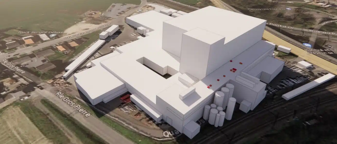
Analysis of the aeraulic and thermal flows of the Aluminium Dunkerque plant through 3D modelling and CFD simulations, in the context of adding an 8th furnace.
The study focuses on optimising the placement of the ventilation systems for the Aluminium Dunkerque plant. CFD numerical simulations were carried out to analyse the fluid flows and assess the aeraulic and thermal conditions of the plant, in order to propose precise recommendations to optimise the placement of the ventilation systems.
The essentials. Aluminium Dunkerque wants to add an 8th furnace to a foundry cooled by natural ventilation (7 furnaces at around 750 °C). An on-site audit (smoke tests, temperature probes, thermal camera) and Dunkerque weather data fed a 3D CFD model. Result: a ridge ventilator above furnace 8 and the closure of a counterproductive louvre bring the temperature under the roof down, at a nearly constant extraction flow rate.
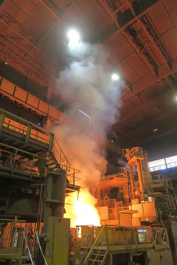
The study concerns the placement of the vents in order to improve the thermal comfort of the Aluminium Dunkerque plant, which has a natural-ventilation cooling system. The plant comprises 7 furnaces and an ingot production line, and to increase the production capacity, the creation of an 8th furnace is being considered. The temperature of these furnaces is around 750 °C and significant hot-air movements are therefore generated inside the plant.
The foundry hall is equipped with 4 large ridge ventilators, 13 static aerators, as well as louvres on some façades of the building. The objective of this study will therefore be to investigate whether the current ventilation system is sufficient for the addition of an 8th furnace, and if not, to find how to remedy it.
A ridge ventilator is a large roof-lantern integrated into the roof structure. Motorless, it discharges the hot air by thermal draught over a wide section, which makes it effective above very hot sources such as a furnace.
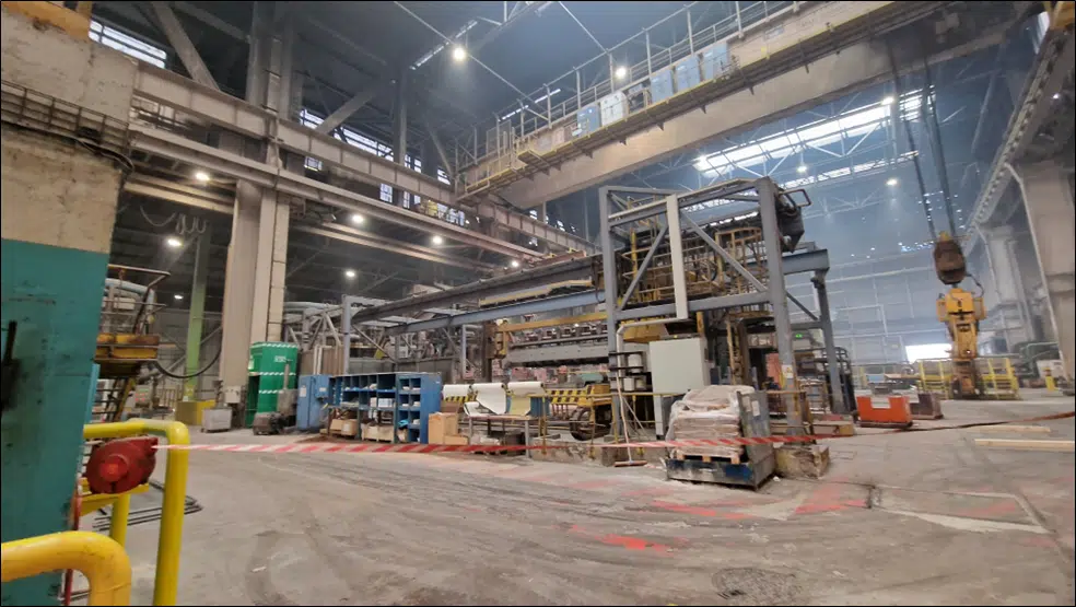
The audit carried out aimed to collect as much information as possible about the operation of the site regarding temperature and air movements. Various tests and measurement tools were used to achieve this goal. The smoke test was carried out using a smoke machine that generated a large amount of smoke in the volume. This made it possible to visualise the macro movements of the air currents inside the site.
The smoke used was harmless to the environment and was generated from a non-polluting water- and glycol-based liquid. Videos were made during these tests to analyse the phenomena observed on site. Air-temperature measurement devices, such as telescopic probes with calibration certification, were used to record the temperatures and air velocities on the site. The results of the smoke tests showed that the air currents near the furnaces are mainly upward.
Next, thermal images were used to highlight the main sources of the thermal phenomena and the various areas that are more or less dense in heat.
The recorded temperatures were compared with the CFD simulation results to verify their consistency.
The emissivity of the various surfaces was taken into account to estimate the temperatures.
All the vents, openings and air passages on the site were identified during the audit. This makes it possible to faithfully reproduce the plant in the simulations, also taking into account the drawings provided. Four types of openings were identified, including fully open doors, louvres on the façades, ridge ventilators and static aerators. The audit also made it possible to identify the overall geometry of the foundry and the various volumes that affect the airflow. This information on the temperatures, air movements, openings and site geometry is essential to understand and faithfully reproduce the plant in the simulations. It will also serve as a basis for formulating recommendations to optimise the aeraulic and thermal conditions on the site.
The climate data from the Dunkerque weather station are of vital importance to define the external climate conditions needed for the study of the plant's ventilation. The information collected includes the wind speed and direction, as well as the average minimum temperature in winter and the average maximum temperature in summer.
In addition, the most extreme recorded temperature peaks are also taken into account. These data play a crucial role in adapting the ventilation and air-conditioning strategies to guarantee the optimal comfort of the plant operators throughout the year.

Computational Fluid Dynamics (CFD) is a numerical method for studying fluid flows in a given environment. This method uses partial differential equations to solve fluid-flow problems, which are often unsolvable analytically.
In the context of buildings, a CFD study can provide information on the air velocities, pressures and temperatures inside and around built spaces. This makes it possible to better understand the aeraulic and thermal conditions, notably in the design of ventilation and air-conditioning systems.
CFD simulations are particularly useful for optimising indoor comfort by ensuring that the airflows are adequate and well distributed, which helps improve energy efficiency and occupant well-being. Geometric modelling is an essential step in CFD simulations. It consists in faithfully representing the geometry of the site or building studied. This makes it possible to define the boundary conditions, such as the type of walls, the surfaces open to the outside, the internal heat inputs, etc. Geometric modelling also makes it possible to simplify the model by removing the elements not relevant to the aeraulic and thermal study, which facilitates the interpretation of the results.
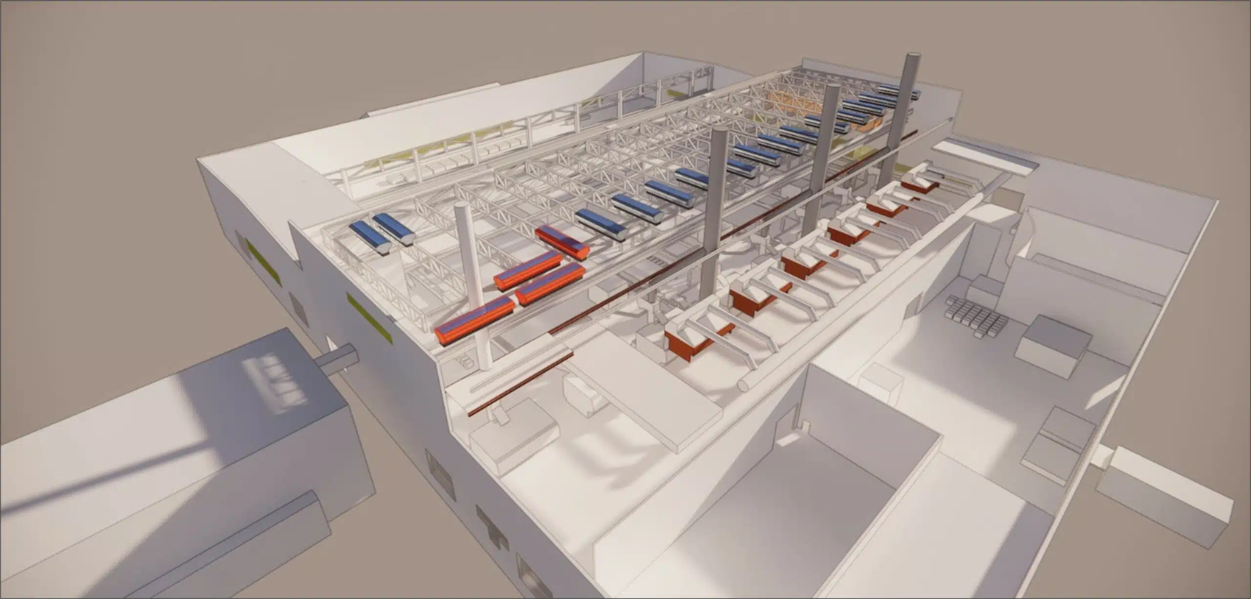
In summary, CFD simulations are used to study fluid flows in the context of building design. They make it possible to optimise the aeraulic and thermal conditions, to improve indoor comfort and to optimise energy efficiency. Geometric modelling and the meshing of the model are key steps in this process, as are the definition of the boundary conditions and the use of appropriate turbulence models.
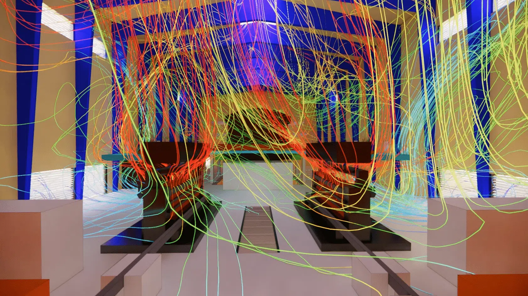
The objective of this study was to verify the correct aeraulic operation of the site following the addition of the new furnace 8. Several scenarios were examined for this purpose. The first scenario was the existing scenario, using the air-extraction systems as they are currently in place, with external conditions based on the weather analysis. However, the results showed an imbalance in the temperature distribution between the north and south sides of the site, due to the absence of an extractor hood for furnace 8 and of a ridge ventilator. The second scenario incorporated additional static aerators above furnace 8. The results demonstrated that the addition of these aerators allowed a faster and more targeted discharge of the heat-laden air, thereby improving the aeraulic operation of the site.
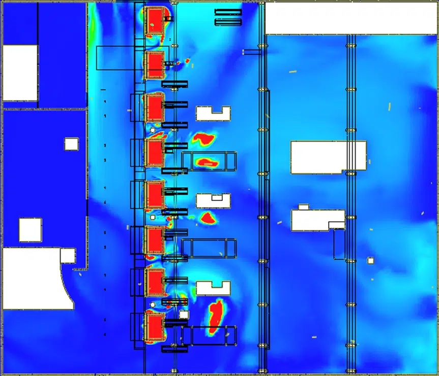
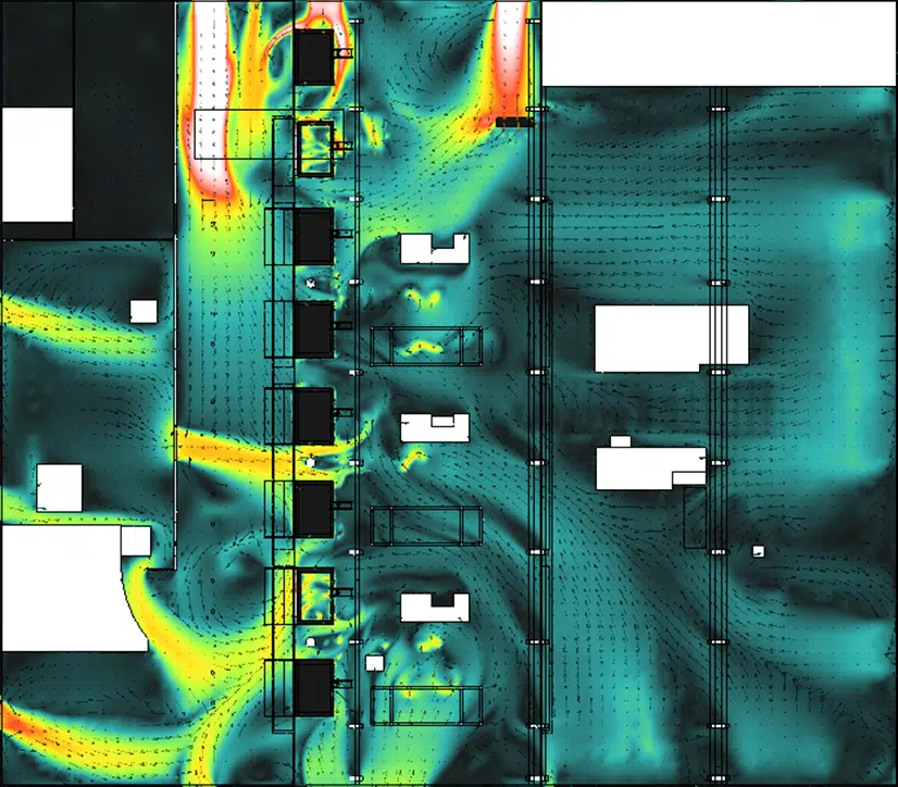
Following the results of the second scenario, the third scenario was studied, involving the closure of a louvre deemed counterproductive. This scenario showed that closing this opening promoted the stratification of the hot air, leading to better thermal draught and a more effective discharge of the heat-laden air. These results therefore demonstrate the importance of correctly placing the air-extraction systems and the ventilation openings in the proper aeraulic operation of the site. The resulting recommendations encourage the addition of targeted aerators to facilitate a more effective discharge of the heat-laden air, and the closure of certain openings to promote an optimal stratification of the hot air.
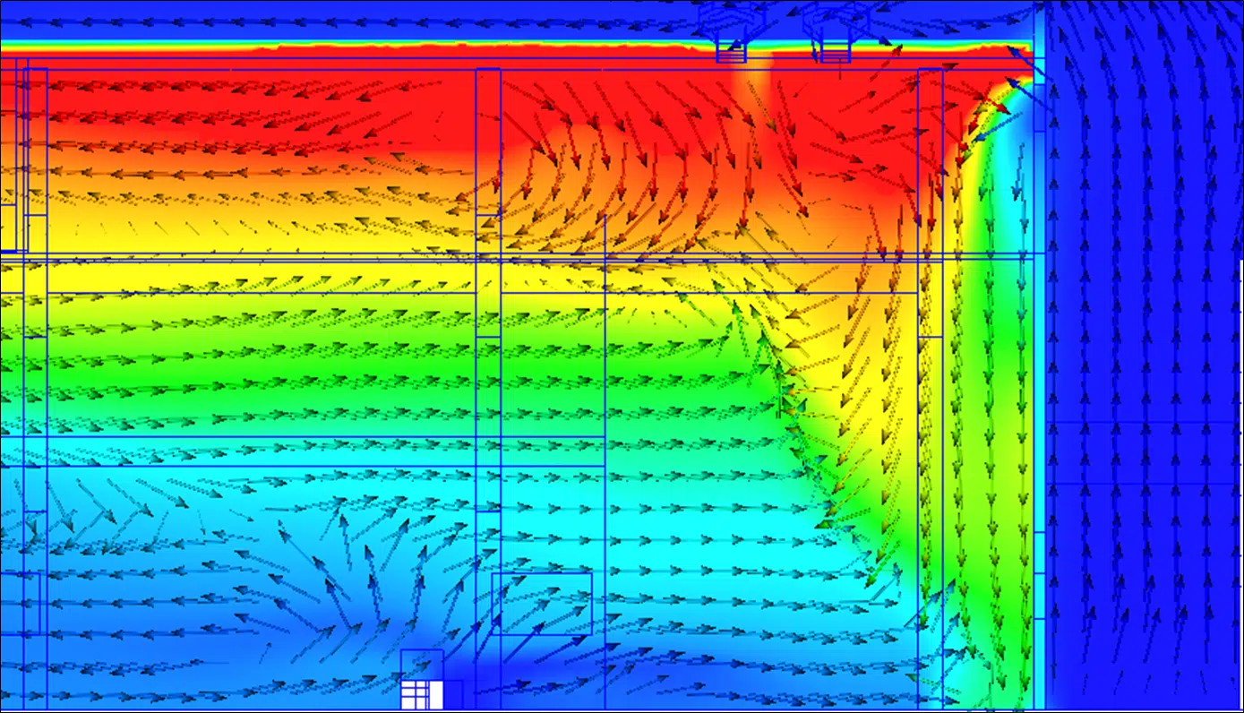
During this study, two configurations were examined to assess the effectiveness of dust extraction in the case of furnace 8 in open-door mode. The first configuration was the baseline configuration, while the second configuration included the addition of static aerators and the closure of the inappropriate louvre. This study relates to our expertise on the study of the propagation of powders and fine dusts.
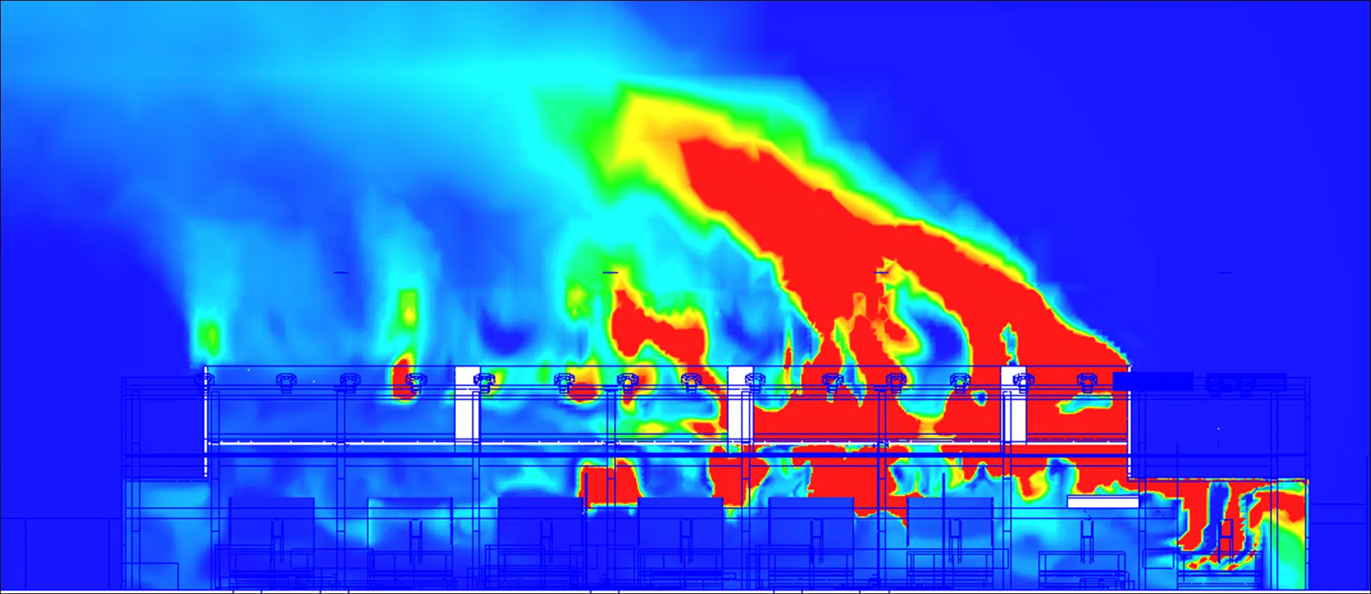
Thermal draught is the upward movement of air caused by its expansion as it heats: lighter, it rises and escapes through the high openings, drawing fresh air in from below. It is the driver of natural ventilation. This phenomenon is part of the sizing of static aerators.
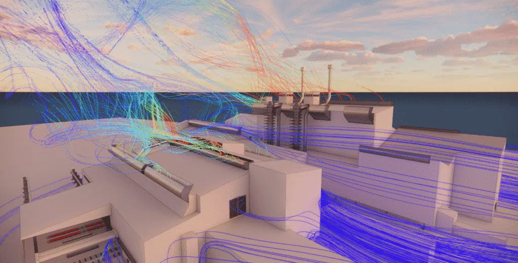
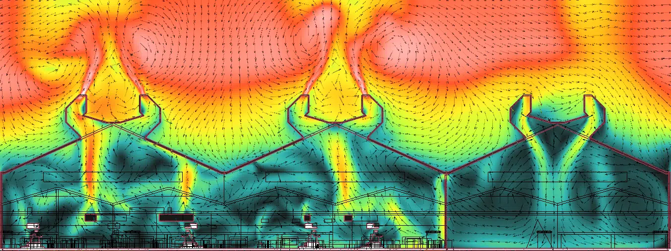
The simulations carried out then included the installation of a new ridge ventilator above furnace 8. The simulation results showed that the newly added ridge ventilator had a significant impact on the airflows. A disappearance of the directed flow from furnace 8 towards the small ridge ventilators already present is observed.
Regarding the temperature distribution, the results indicate a distribution similar to that of the previous scenarios, but with a clear drop in temperature under the roof thanks to the presence of the ridge ventilator.
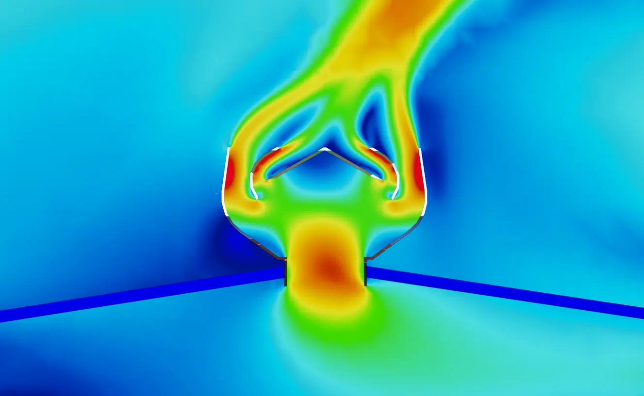
The temperature under the roof drops considerably thanks to the rapid discharge of the hot air laden with heat by the ridge ventilator. The results also highlight that the total extraction flow rate remains broadly constant, with a slight increase compared with the existing configuration. These results demonstrate the effectiveness of the ridge ventilator added above furnace 8 in rapidly discharging the heat-laden hot air. This modification therefore helps to improve the airflows and the thermal conditions in the building.
The radiative study, as part of the thermo-aeraulic analysis of a plant, makes it possible to better understand the impact of thermal radiation, to assess the interaction between radiation and convection, and to identify the areas where adjustments are needed to optimise the thermal conditions inside the plant. This makes it possible to improve worker comfort, to prevent overheating problems and to optimise the energy efficiency of the plant.
Thermal radiation is the transfer of heat by electromagnetic waves, without contact or intermediate air. A very hot furnace thus directly heats the walls facing it, in addition to the air: it is an input distinct from convection, to be treated separately.
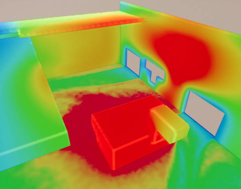
Simulations were therefore carried out to assess the radiative transfer from furnace 8 towards the surrounding walls in two different scenarios. The first scenario corresponds to the usual configuration where furnace 8 is closed. The results showed that significant radiative fluxes were received by the north façade, the wall facing the furnace and the low roof, with maximum temperatures reaching about 70 °C. The second scenario concerns furnace 8 open with an internal temperature of 500 °C to account for the cooling of the open furnace. The same zones are then also subject to significant radiative fluxes with maximum temperatures of around 75 °C.
These results demonstrate the significant impact of the radiative transfer from furnace 8 towards the surrounding walls. They highlight the zones that receive the largest radiative fluxes, notably the north façade, the wall facing furnace 8 and the low roof.
Our company's expertise made it possible to find technical solutions for adding a new furnace to the plant and to improve thermal comfort for the workers. The modifications made resulted in a significant reduction in temperatures under the roof and in the work areas, as well as the improvement of ventilation by reducing the hot-air flows in specific locations.
The radiative analysis also made it possible to identify three zones where the radiative transfer is more intense, which may represent a danger to the workers. These results help improve the understanding of the airflows and thermal conditions, and make it possible to formulate recommendations to optimise ventilation, temperature and, more generally, the working conditions inside the site.
Key takeaway. Adding a heat source to a naturally ventilated hall is not just a matter of cutting one more opening: it is the position of the aerators and the targeted closure of certain openings that restore an effective thermal draught, convection and radiation taken together.
Natural ventilation, ridge ventilators and furnace radiation in an aluminium plant.
Yes, provided the ventilation is resized. The study shows that by adding a ridge ventilator above furnace 8 and closing a counterproductive louvre, the site discharges the hot air of the eighth furnace without any fan. A similar approach was carried out on our project natural ventilation of a steel plant.
A badly placed opening can short-circuit the thermal draught by letting air in where the hot air should rise. By closing it, the stratification of the hot air is promoted and a more effective discharge through the roof aerators is achieved.
It quantifies the radiative transfer from the furnace to the walls, distinct from convection. It identified three zones (north facade, wall facing the furnace, low roof) receiving up to 75 °C, which may represent a risk to the operators.
Placed as close as possible to the hot source, it discharges the heat-laden air by thermal draught before it spreads under the roof. The total extraction flow rate stays nearly constant, but the hot air leaves faster and closer to the furnace.
The thermal camera measures the real surface temperatures on site; comparing them with the simulation results makes it possible to verify the consistency of the model and to calibrate it before exploring scenarios that were not carried out.
Explore our expertise, projects and technical papers to go further than the FAQ.
The study concerns the optimal placement of the vents in order to improve the thermal comfort of the Aluminium Dunkerque plant, which uses a natural-ventilation cooling system. The aim is to determine whether the current ventilation system is sufficient for the addition of an 8th furnace and, where appropriate, to propose solutions. Various preliminary measurements were carried out, such as smoke tests to observe the air movements, temperature measurements and thermal images to identify the heat sources. These data were used to create a 3D model of the plant in which CFD numerical simulations were carried out. CFD simulations make it possible to study fluid flows and to simulate the aeraulic and thermal conditions of the plant. The results showed that the addition of certain aerators would allow a faster and more targeted discharge of the hot air, thereby improving the aeraulic operation of the site. In conclusion, this study made it possible to determine the optimal placement of the vents to improve the thermal comfort of the Aluminium Dunkerque plant ahead of the addition of an 8th furnace. The CFD simulation results provided precise recommendations to optimise the energy efficiency and well-being of the plant operators.
CFD expertise, delivered projects and technical dossiers: the whole Industries field in one place.
The easiest way is to talk it through together. Our engineers will reply with an initial technical read.