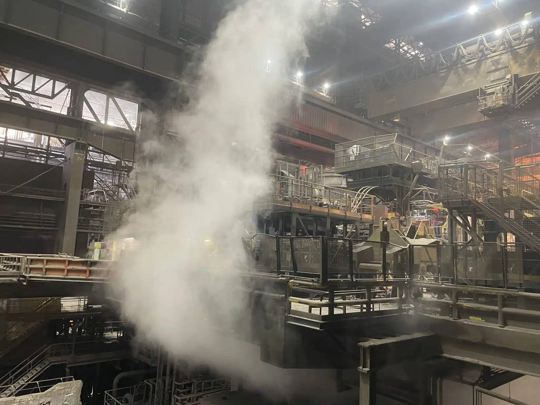
CFD analysis of the saturated mist on a continuous casting line in a steelworks: field audit, 3D modelling and optimisation of the capture to eliminate leaks and production stoppages.
EOLIOS's expertise in CFD simulation (Computational Fluid Dynamics) and in the optimisation of industrial capture and ventilation systems was mobilised to address the challenges linked to the management of saturated mist on a continuous casting line in a steelworks. Inherent to high-temperature processes, these phenomena represent strong constraints in terms of safety, working conditions and production continuity.
EOLIOS draws on recognised experience in the study of complex flows in industrial environments, gained from numerous field missions and CFD simulations applied to installations with high operational stakes. This expertise makes it possible to provide reliable, pragmatic and economically optimised answers, serving informed decision-making.
The essentials. On a continuous casting line in a steelworks (Brandenburg, Germany), saturated mist laden with moisture and heat was escaping under the first-floor deck, causing corrosion, loss of visibility and production stoppages. EOLIOS conducted an on-site audit (measurements, smoke tests, thermography), then built a calibrated 3D CFD model of the lines and the hall. The simulations locate the leaks, the parasitic air inlets and the stagnation zones, and demonstrate that simple structural improvements, without increasing the extraction power, raise the depression of the cabins and reverse the airflow trend. An advanced configuration pushes mist control to close to 100%.
Industrial mist is a major multidisciplinary challenge, at the crossroads of operator safety, comfort and air quality, but also process continuity and the durability of installations.
Saturated mist consists of plumes of air laden with water vapor at saturation, generated in contact with the hot slabs. As it cools, this vapor condenses into fine visible droplets that reduce visibility, promote the corrosion of metal surfaces and disperse through the hall.
Firstly, the presence of mist, laden with moisture — an essential driver of electrochemical corrosion — causes risks of material degradation of the plant. When it settles on metal surfaces, it forms a water film that allows chemical reactions between the metal and oxygen to occur. This attack is often accelerated by impurities dissolved in the mist, such as salts, acids or dust, which increase its conductivity. Repeated exposure thus leads to cumulative effects: uniform corrosion, localised pitting and degradation of coatings or seals, which reduces the durability and integrity of the metal equipment.
This material-degradation aspect is a major risk to the operation of the plant. But beyond it, mist also presents a risk to the safety and health of workers. The combination of moisture and heat generates plumes that can degrade visibility, disrupt the airflows and alter the thermal conditions around the work zones and equipment. These phenomena can increase the risk of accidents (reduced visibility, difficulty handling equipment) and cause health issues (irritation, respiratory problems).
The presence of mist thus acts as an overall disruptive factor, liable to reduce the safety, the efficiency and the durability of industrial infrastructure.
A safety challenge. Beyond the material damage, the combination of moisture and heat reduces visibility and can cause irritation and respiratory problems. Mastering the mist means, first and foremost, protecting the operators who work close to the line.
It was in the context of a continuous casting installation in a steelworks located in the Brandenburg region of Germany that EOLIOS was commissioned. In this plant, malfunctions of the existing capture system caused a significant accumulation of mist under the first-floor deck, leading to regular production stoppages. EOLIOS stepped in to analyse the real operation of the system in detail, identify the causes of these faults and propose effective and lasting solutions.
To master the challenges linked to industrial mist, an approach combining on-site measurements (through an audit) and numerical flow modelling (CFD, Computational Fluid Dynamics) is favoured today. CFD provides a three-dimensional, dynamic view of the flows, essential to precisely identify the critical zones of heat and vapor accumulation, air recirculations, capture deficits at source and the interactions between thermal plumes and ventilation systems. It thus makes it possible to quantitatively assess the effectiveness of the existing devices and to understand their limits under real operating conditions.
One of the main strengths of CFD lies in its ability to virtually test different layout scenarios or modifications of the installations: repositioning or sizing of the capture points, adjustment of flow rates, addition of baffles, changes to the geometries or the ventilation strategies. This numerical exploration, fast and non-intrusive, makes it possible to objectively compare several solutions, optimise their performance before implementation and significantly reduce the technical and financial risks associated with on-site trials.
In addition, CFD is a particularly relevant decision-support tool for reconciling airflow performance and energy efficiency. It makes it possible to anticipate the impacts of the envisaged solutions on energy consumption, the building's thermal balances and operator comfort, thus contributing to a more sober and sustainable design of the ventilation systems.
Learn more: what is CFD simulation?The study presented had the following main objectives:
understand the thermal and airflow phenomena at the origin of the mist leaks;
analyse the real operation of the existing capture network;
assess the effectiveness of different improvement configurations;
identify technically efficient and relevant solutions.
For this, an approach combining on-site audit, analysis of the duct networks and CFD simulation was implemented.
A thorough audit was carried out directly on the continuous casting line to precisely characterise the phenomena under real operating conditions. Measurement campaigns were performed around the machine to quantify air velocities, temperatures and humidity, providing a reliable and representative initial state. Smoke tests were also conducted to qualitatively visualise the airflow trajectories and the leak paths of the mist, and thus identify the priority escape zones and the malfunctions of the existing capture devices.
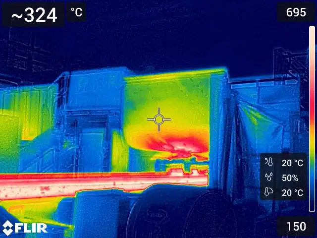
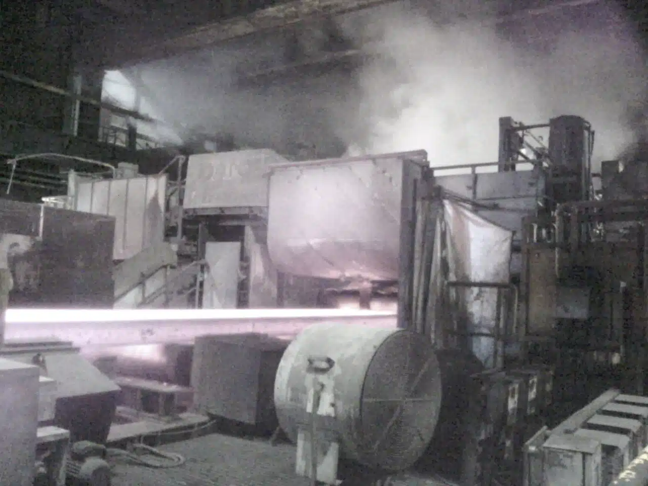
Beyond the data collection, the on-site audit is a key step to grasp the real operation of the installation, in an often complex and evolving environment. It makes it possible to confront the theoretical schemes and existing drawings with the reality of the field, and to integrate the effects of operating practices, access constraints, transient situations and weather conditions — all elements rarely fully documented. This detailed knowledge of the site is indispensable to correctly interpret the observed phenomena and to avoid oversimplifying assumptions far from reality.
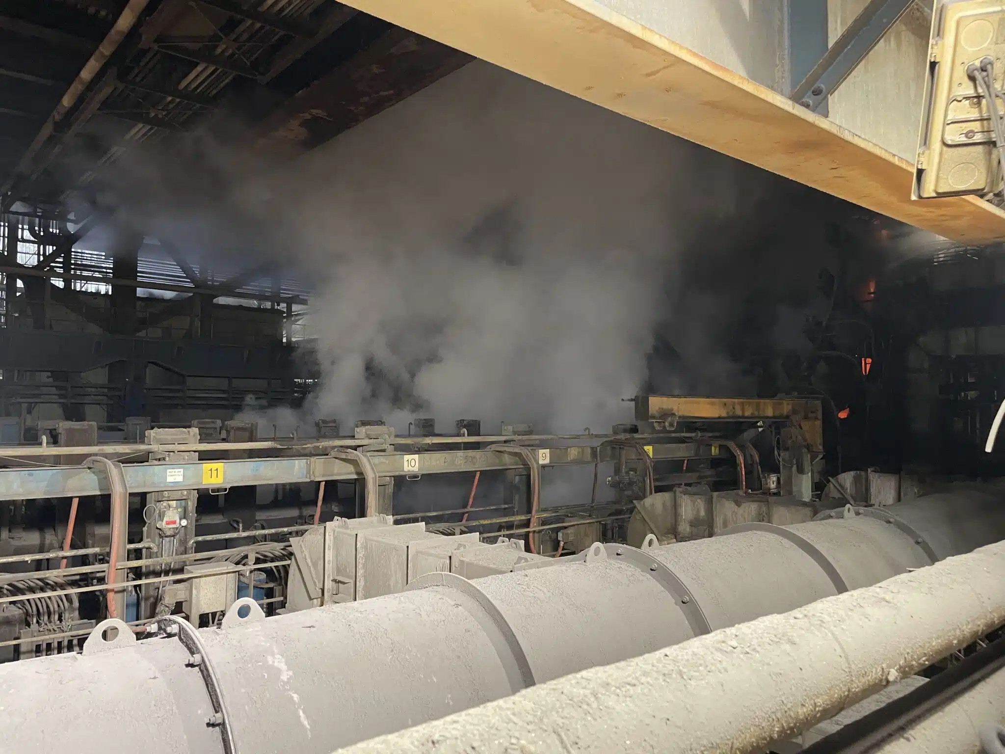
The field observations from the audit thus formed an essential basis to feed, calibrate and validate the numerical CFD model. They guarantee the consistency between the simulation and the real behaviour of the system, reinforcing the reliability of the results and the relevance of the proposed solutions. The on-site audit therefore appears as an unavoidable prerequisite for any approach to the analysis and lasting optimisation of industrial-mist problems.
The 3D CFD modelling rests on a rigorous geometric foundation, built from the existing drawings supplemented by surveys and observations carried out during the on-site audit. This step is decisive, because the quality and representativeness of the model directly condition the relevance of the results obtained. The aim is to realistically reproduce the air paths, the extraction routes, the duct networks and their interfaces with the mist-generation zones, in order to best reflect the real operation of the installation. This calibrated model is an industrial digital twin: a virtual replica of the installation that makes it possible to test improvement scenarios and predict their effects before any works.
Based on the collected data and the documents supplied, EOLIOS developed a detailed 3D CFD model incorporating the geometry of the machine studied, its immediate environment and all the equipment influencing the airflow of the site. This includes in particular the ventilation systems, the heat sources, the neighbouring machines and all the elements that obstruct or guide the flows, such as airflow masks, screens or metal structures.
The level of geometric detail is chosen with care in order to faithfully represent the elements with a significant influence on the velocity, temperature and vapor-concentration fields, while rationalising the secondary details whose impact on the flows is negligible. This balance between precision and simplification makes it possible to keep the computation times under control, ensure the numerical robustness of the simulations and guarantee results usable for the analysis of the phenomena and for decision support.
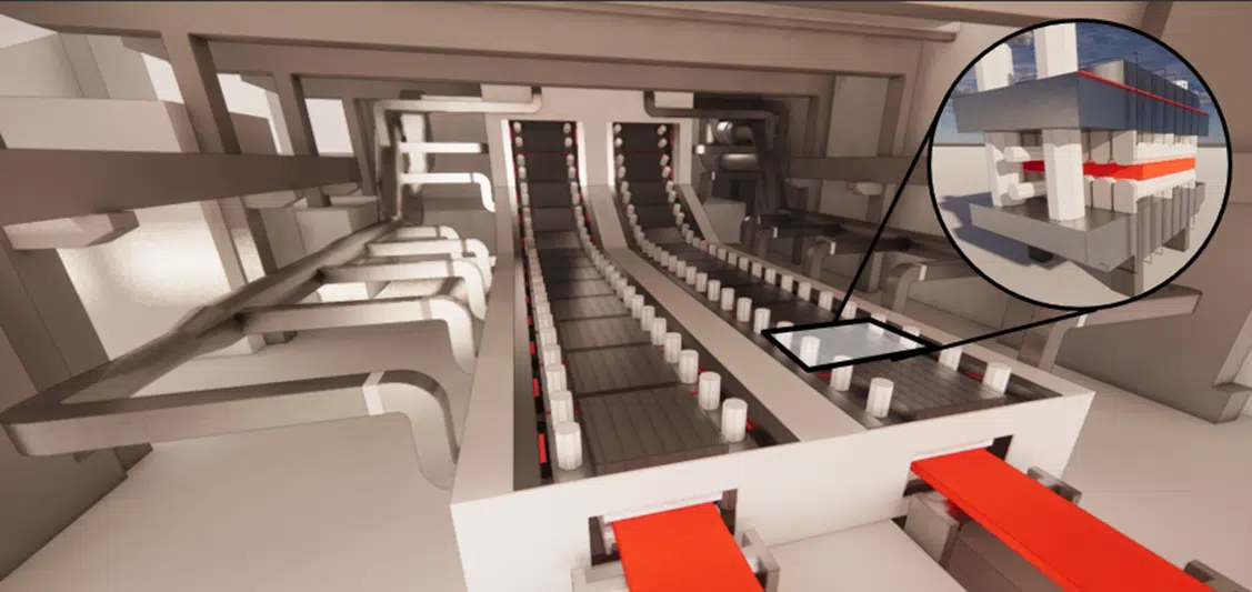
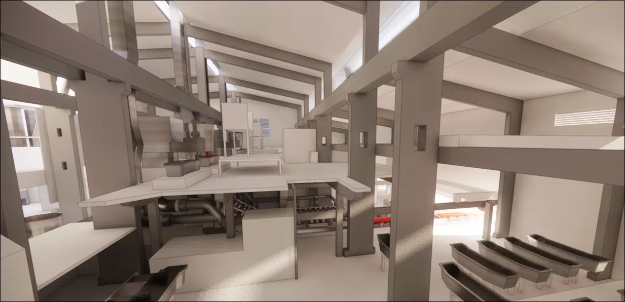
In practice, the CFD approach follows a structured iterative process in several successive steps: building the geometric model, defining the boundary conditions and properties, numerical resolution, then detailed analysis of the flow, temperature and humidity fields. This cycle is completed by a calibration phase from the field measurements, before undertaking iterations dedicated to the study of improvement configurations.
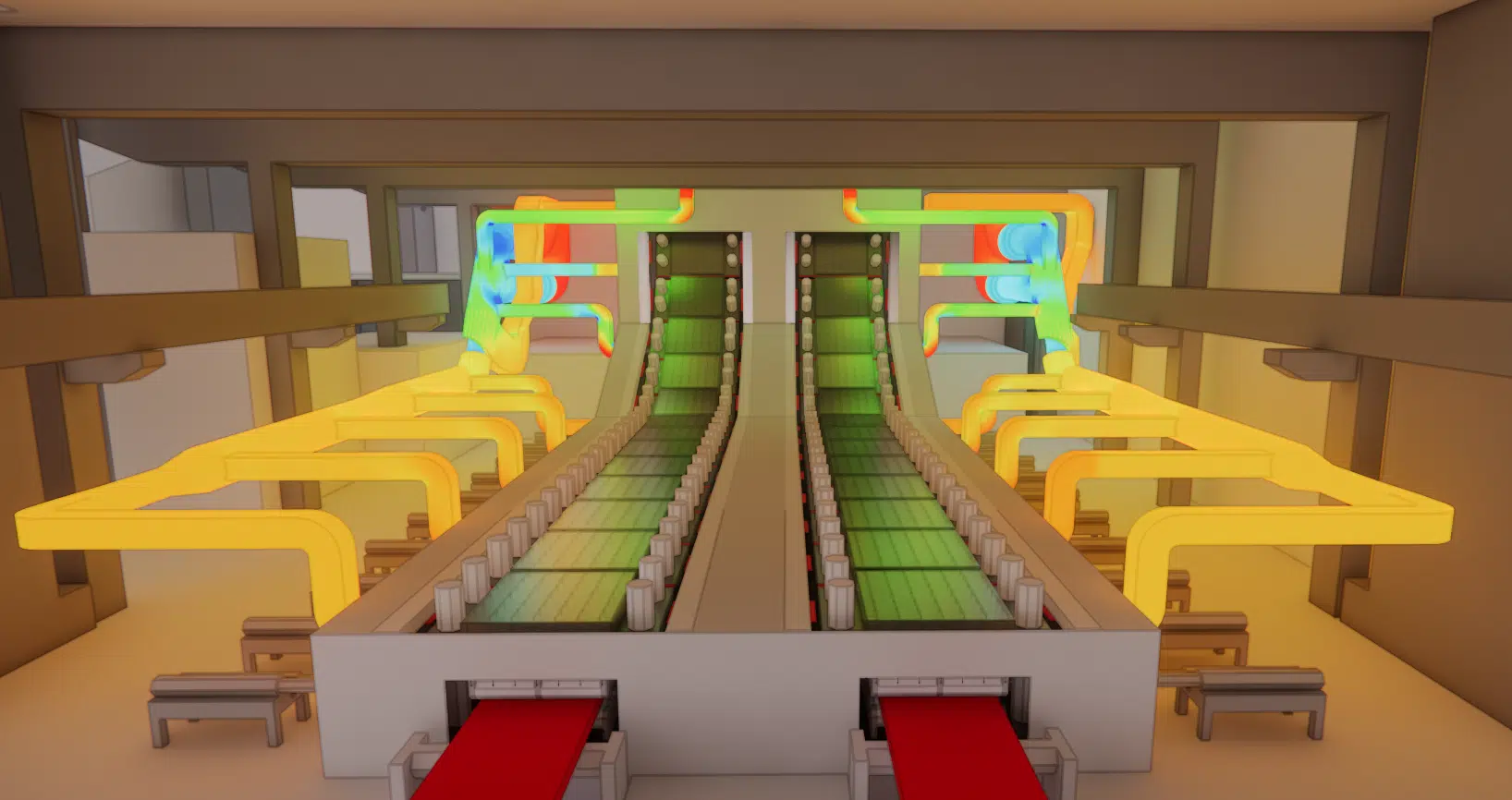
The calibration phase is a key step of the approach, because it guarantees the consistency between the simulation results and the real behaviour of the system. Its aim is to adjust the boundary conditions and the modelling assumptions in order to obtain a satisfactory match between the calculated quantities and the measurements taken in situ during the audit, as well as the data supplied by the project management.
This calibration rests on building a numerical model faithfully reproducing the main physical phenomena at play, in particular the airflow, the heat transfers and the evolution of humidity within the volume studied. The model integrates both the internal sources linked to the processes and the equipment, and the exchanges with the external environment, taking into account key parameters such as extraction flow rates, surface temperatures of the elements, weather conditions and vapor-generation mechanisms.
Once the model is calibrated and validated, it can be used as a reliable predictive tool to study the impact of different modifications (evolution of flow rates, geometries, capture or ventilation devices) and analyse the new flow dynamics within the system, in support of technical decision-making.
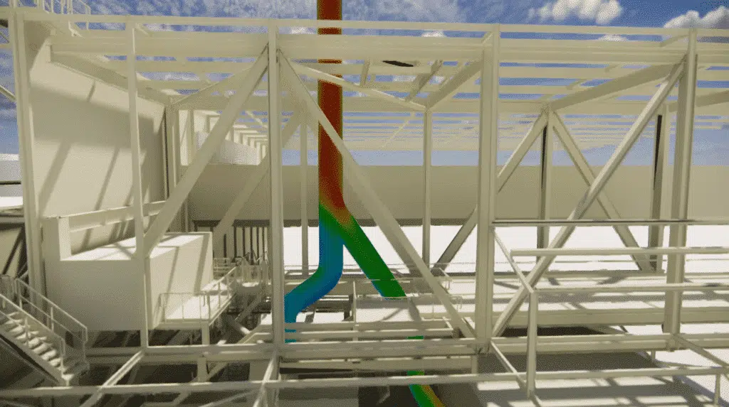
The analysis of the pressure losses within the extraction-duct networks is a fundamental step for the reliable determination of the flow rates actually available at the capture points. In complex industrial installations, the total pressure losses result from the combination of linear losses linked to the duct lengths and singular losses caused by changes of section, bends, tees, branch connections, control devices, as well as the fouling state of the internal walls. These cumulative effects can lead to pressure losses well above the initial design assumptions or the nominal values used in operation.
Pressure loss refers to the drop in pressure undergone by the air as it flows through a duct network: friction along the walls, bends, tees, branch connections, fouling. If it exceeds the pressure available from the fan, the extraction flow rate collapses and capture at source is no longer ensured.
A detailed characterisation of the network makes it possible to confront the theoretical fan curves with the real operating conditions, to identify the flow-distribution imbalances between the different branches and to quantify the gaps between the expected capture flow rates and those actually achievable. This approach is indispensable to establish a coherent airflow balance, assess the operating margins of the ventilation equipment and highlight the structural limitations of the existing network.
Within the CFD simulations, this analysis makes it possible to define realistic and physically representative boundary conditions, in line with the effective extraction capacities of the system. It is thus an essential prerequisite to ensure the validity of the numerical results, correctly interpret the observed phenomena and base the technical recommendations on a rigorous, quantitative assessment of the extraction-network performance.
The study highlighted that the effectiveness of a capture system is not limited to the available extraction flow rate alone, but also depends on the dynamics of the airflows and their origin. In certain configurations, a significant part of the extracted air can come from peripheral or non-critical zones. This external air intake, lightly laden with mist or pollutants, reduces the overall capture efficiency by mobilising part of the extraction capacity without contributing to the removal of the emissions from the zones actually concerned.
These results underline the importance of a precise design and sizing of the capture systems, integrating not only the flow rates but also the effective circulation of the air in the production environment. Targeted control of the flows makes it possible to concentrate the extraction on the mist-generating zones, improve the overall performance of the device and limit energy losses, while guaranteeing safe and optimised working conditions for the operators.
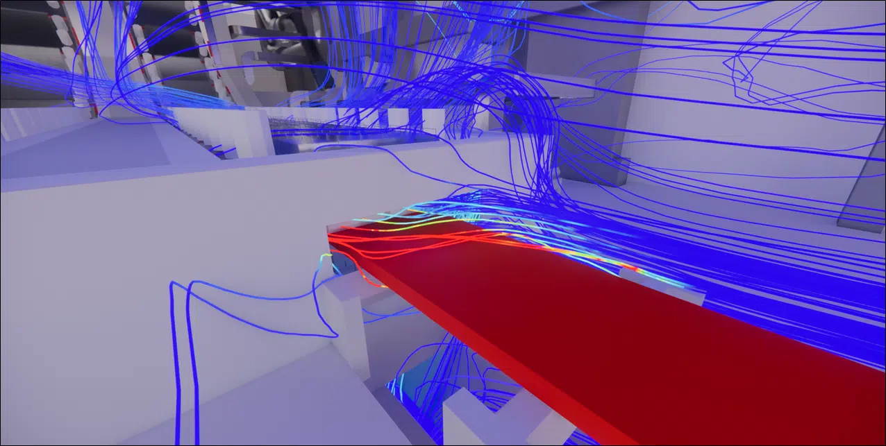
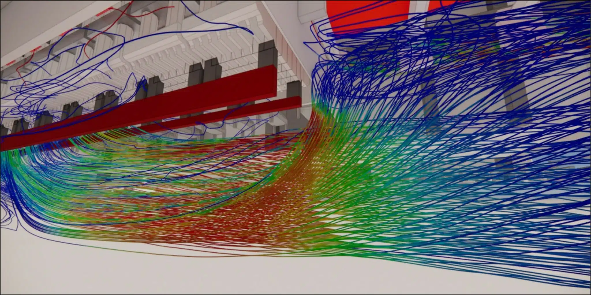
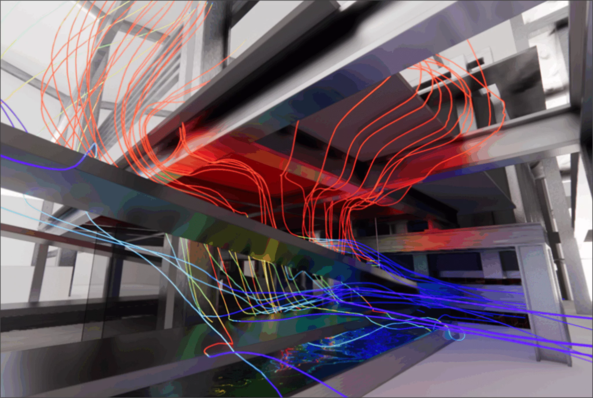
At the mist cabin, the simulations reveal that the depression generated is relatively low. As a result, part of the mist produced in contact with the hot slabs escapes between the segments, forming rising plumes that accumulate under the first-floor deck.
The mist-laden air is then forced to circulate around the deck, while rushing into openings such as the stairwells and duct passages. This path explains the significant stagnation observed under the platform and the presence of visible mist in zones far from its initial source.
The results from the CFD simulations faithfully reproduce these phenomena, both in terms of air velocities and of thermal stratification and humidity distribution, thus confirming the relevance and reliability of the modelling for analysing the flows and guiding the optimisation of the capture systems.
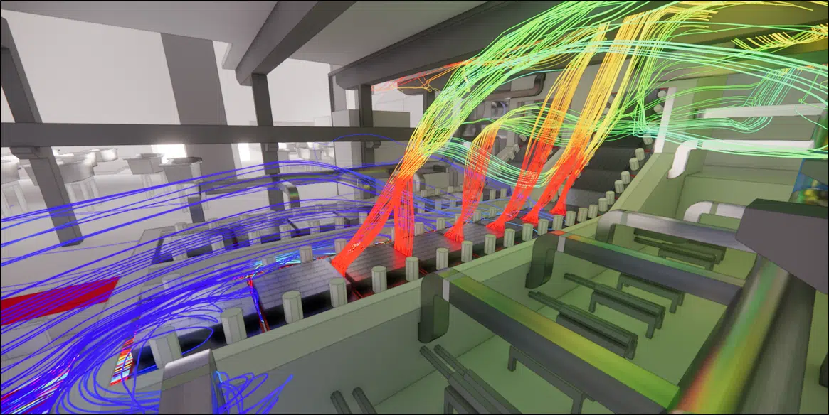
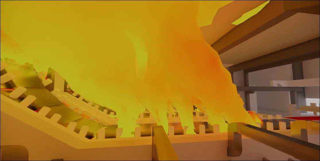
Following the first simulations, several simple structural improvements, requiring no modification of the mist-capture system, could be proposed. Their aim is to reduce the mist escapes into the hall and consequently improve the machine's mist capture. Several beneficial effects emerged.
First of all, an increase in the depression in the cabins is observed. Strengthening the depression improves the effectiveness of capture at source by favouring the extraction of the vapor-laden flows before their dispersion into the hall. This action helps limit leaks towards the adjacent zones, reduce accumulations under the decks and improve the visibility and working conditions of the operators. It must, however, be sized with care to ensure an optimal airflow balance and avoid undesirable impacts on comfort, flow stability or energy consumption.
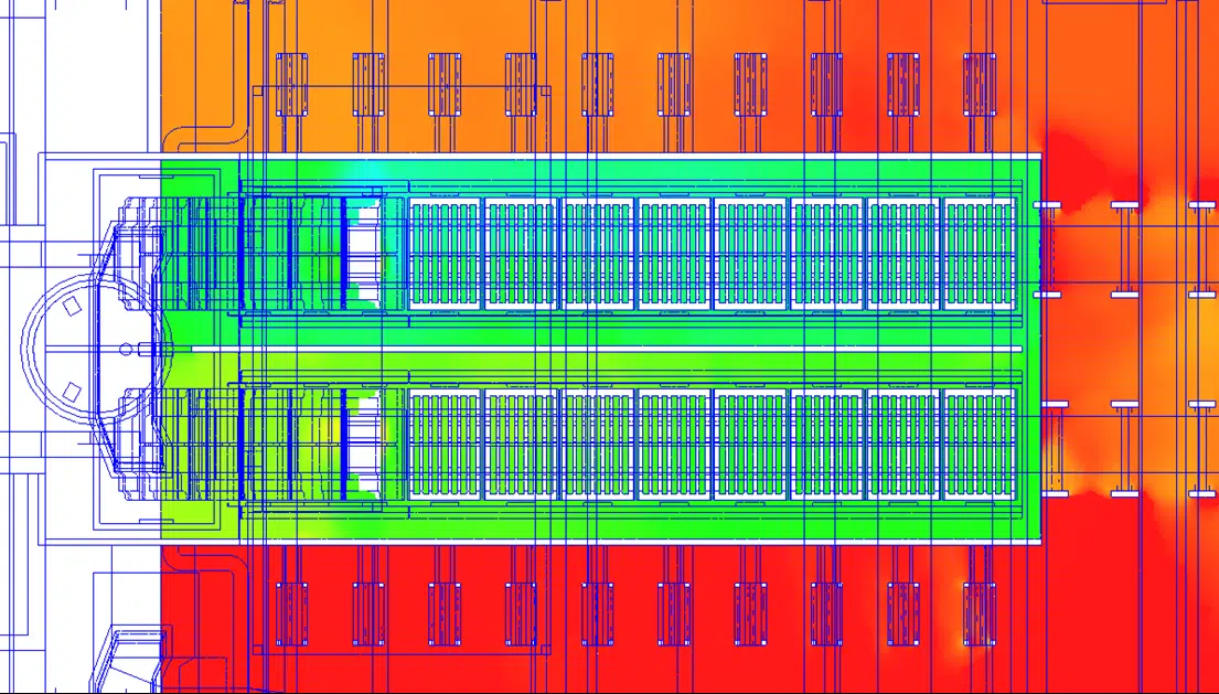
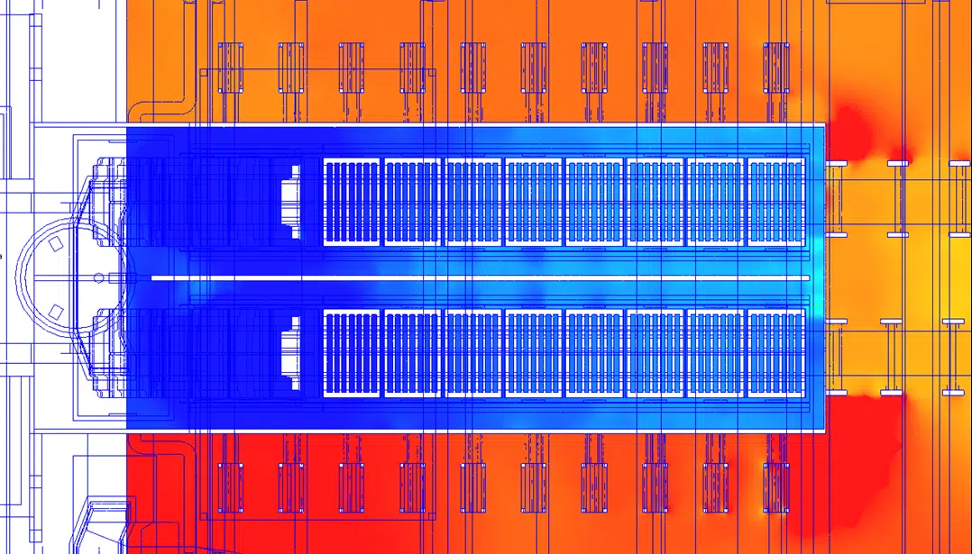
This depression is accompanied by a reversal of the airflow trend above the mist cabins. The shift from rising streams of hot air to descending streams of fresh air makes it possible to counter the natural rise of the mist and contain its dispersion towards the upper levels. This airflow reversal favours the downward driving of the vapor-laden flows towards the capture zones, improves the control of the thermal plumes and helps stabilise the flow conditions around the cabin. It thus contributes to a marked improvement in visibility, thermal comfort and safety in the adjacent work zones.
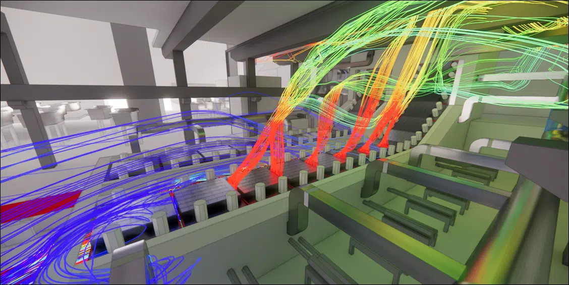
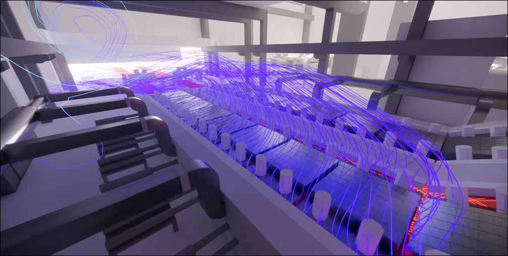
All in all, these two elements allow most of the vapor flow diffused into the hall to be captured by the extraction system. The cabin is then able to intercept the majority of the mist before its dispersion into the environment. This significantly improves the overall efficiency of the system, limits leaks towards the neighbouring zones and reduces the load on the general ventilation devices. It thus contributes to better control of the vapor plumes, a lasting improvement in working conditions and a reduction in the associated energy losses.
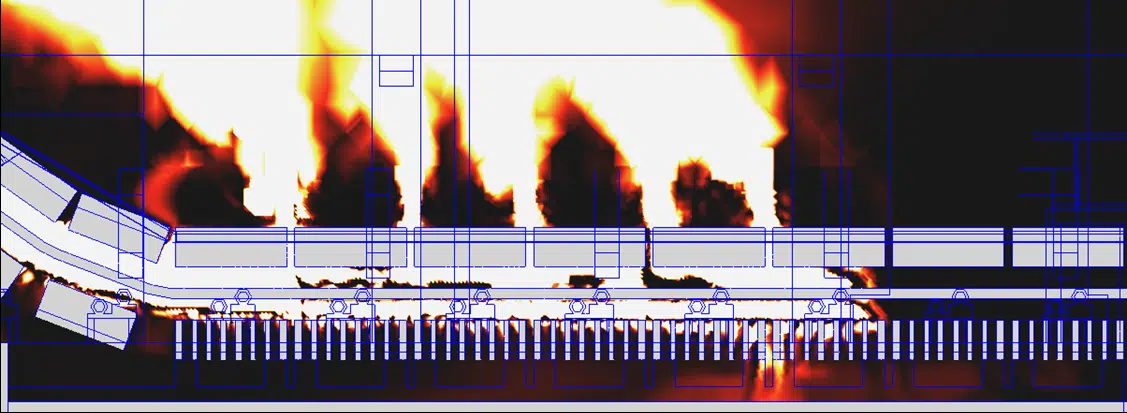
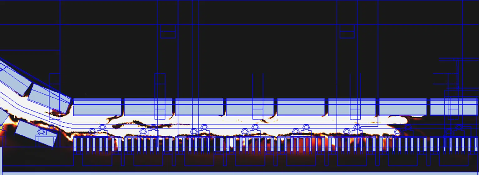
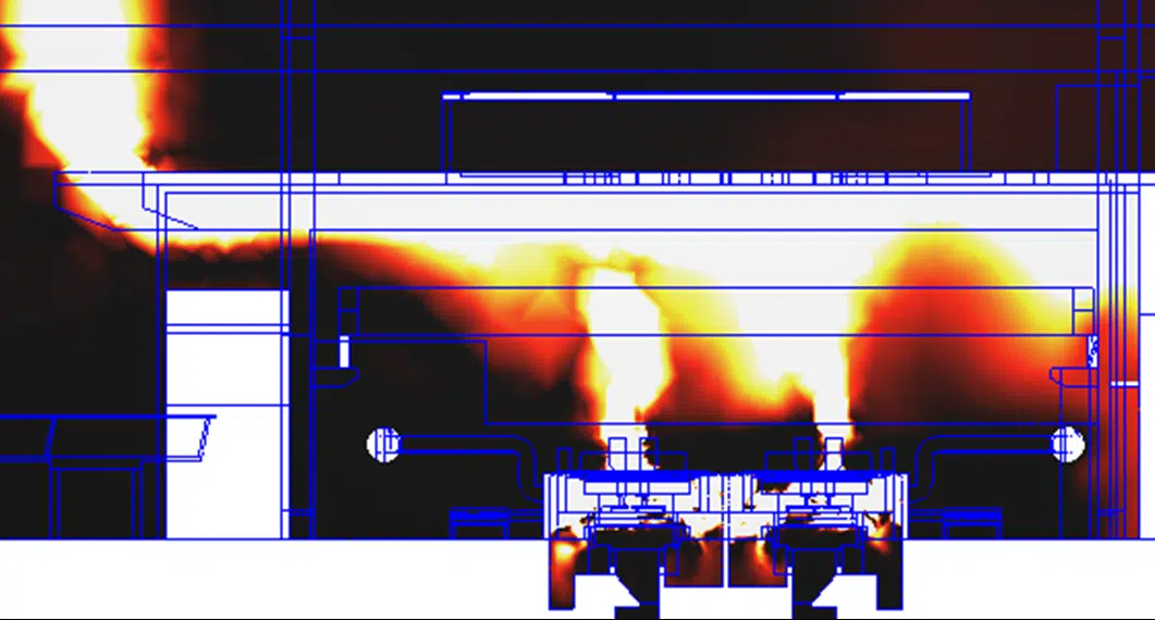
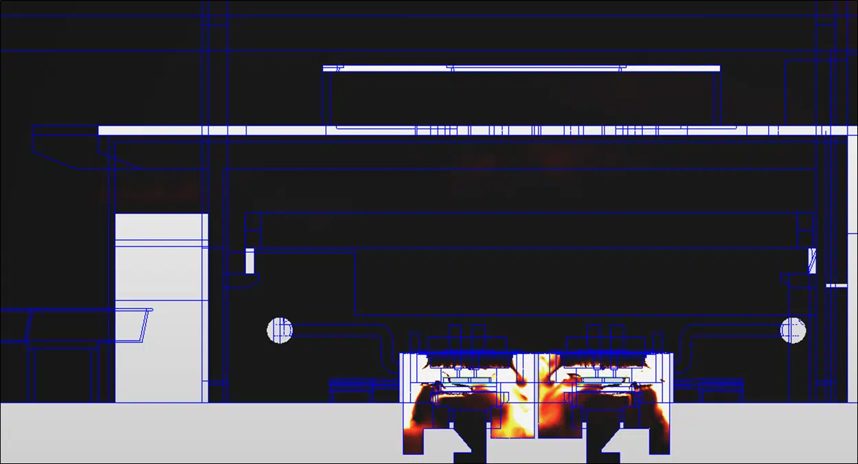
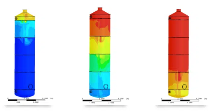
In addition, the better control of the heat and mist flows makes it possible to limit the thermal stratification of hot air under the roof. This reduction of the temperatures in the upper part helps preserve the structures and equipment, limit condensation and corrosion phenomena, and improve the overall thermal comfort of the building. It also contributes to better airflow stability and can lead to a reduction in ventilation needs and the associated energy consumption.
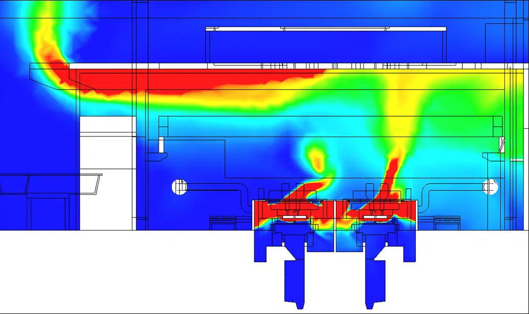
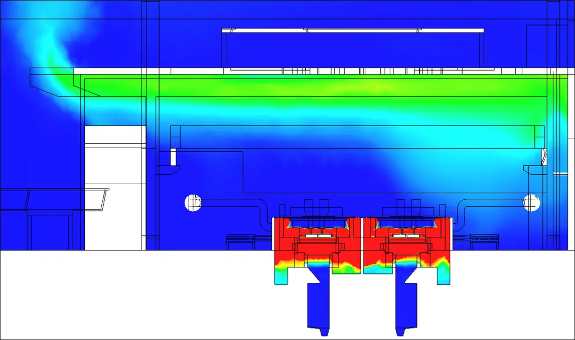
Despite these improvements, a slight escape of mist remains at the vertical part of the casting. It nevertheless stays limited and does not call into question the overall effectiveness of the device, the residual flows being quickly diluted and not causing any significant degradation of the operating or safety conditions.
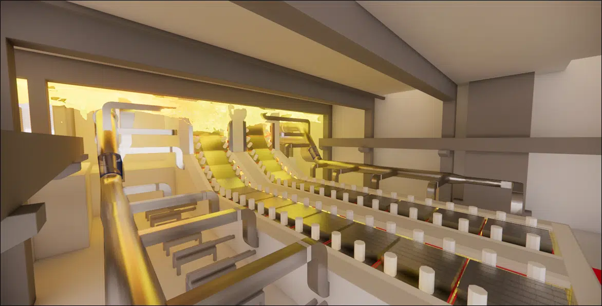
A more advanced configuration, combining the simple structural improvements with the addition of new capture devices, was also studied. This solution allows near-total control of the mist, including on the vertical part of the casting, with an overall efficiency close to 100%. It provides a maximum level of performance and strong robustness against operating variations, virtually eliminating any risk of residual escape.
However, this approach must be put into perspective against the simpler solution studied previously, which already made it possible to very significantly reduce the mist emissions and markedly improve the operating conditions, for a clearly lower investment cost and implementation complexity. This first solution thus offered a particularly relevant compromise between performance, simplicity and cost, while addressing the main safety and comfort challenges.
The addition of complementary devices is therefore justified mainly in a logic of maximum performance or high operational requirements, when the objective is to eliminate almost all residual emissions or to secure the installation against highly variable operating conditions. The choice between these two approaches is thus a technical-economic trade-off, the simple solution being an effective, optimised answer, while the reinforced solution brings a higher level of control at the price of increased investment and complexity.
The results of the study made it possible to identify solutions that are at once simple, robust and economically optimised, emphasising the control of the airflows and the removal of the parasitic inlets before considering any increase in the ventilation power. This approach favours the effectiveness of the interventions, minimises costs and immediately improves the performance of the existing device.
In parallel, complementary analyses highlighted more complex solutions, offering even finer control of the flows and maximum efficiency, but requiring a higher investment. These options make it possible to achieve near-total control of the mist and a lasting optimisation of the environmental conditions in the production hall.
EOLIOS's intervention thus provided the client with a complete understanding of the physical phenomena at play, the priority levers for action and the expected gains. This structured approach directly contributes to improving working conditions, the reliability and the safety of operation, while strengthening the overall performance of the installation. It also offers a solid decision-making tool for choosing between immediate, economical solutions or more ambitious and lasting optimisations.
Saturated mist, the contribution of CFD and the EOLIOS method on a continuous casting line.
Laden with moisture and heat, mist promotes the corrosion of metal equipment, degrades visibility and the working conditions of operators, and disrupts the airflows. On the installation studied, its accumulation under the first-floor deck caused regular production stoppages.
CFD offers a three-dimensional, dynamic view of the flows: it locates the zones where heat and vapor accumulate, the recirculations, the parasitic air inlets and the capture deficits at source. It makes it possible to test several improvement configurations virtually before any works, which a global calculation cannot do.
The audit provides a reliable initial state: air velocities, temperatures and humidity measured around the machine, and visualisation of the leak trajectories through smoke tests. These data are used to calibrate and validate the numerical model so that it reflects the real behaviour of the installation.
Yes. The simulations show that simple structural improvements are enough to increase the depression in the cabins and reverse the airflow trend above them, driving the mist back towards the capture points. Parasitic air inlets are removed first, before considering any increase in fan power.
The simple solution sharply reduces mist escapes at low cost and complexity. The complex solution, combining structural improvements with new capture devices, achieves near-total control (close to 100%) but requires a higher investment. The choice is a technical-economic trade-off.
Explore our expertise, projects and technical papers to go further than the FAQ.
Study summary
The study carried out by EOLIOS made it possible to finely understand the mechanisms of generation, dispersion and capture of the saturated mist within a continuous casting installation. Relying on an analysis of the real operating conditions and on CFD simulations representative of the existing installation, the main malfunctions of the capture system were identified.
The work highlighted that targeted structural improvements, without a significant increase in the extraction flow rates, could already lead to a very large reduction of the mist escapes and a marked improvement of the operating conditions. More advanced solutions were also assessed to reach a maximum level of control, allowing the client to have objective elements to arbitrate between performance, simplicity and investment.
This approach resulted in robust technical recommendations adapted to the industrial context, contributing to operator safety, the reliability of the installations and the overall performance of the site.
CFD expertise, delivered projects and technical dossiers: the whole Industrial process field in one place.
The simplest thing is to talk it through together. Our engineers reply with an initial technical read.