Generator Sets
Home » Industrial Process » Generator Sets
EOLIOS performs CFD simulations for generator sets.
We intervene at different levels of expertise for the design of premises and the optimization of generator sets.
- Study of pressure losses
- Sizing natural ventilation
- Study of NOx diffusion
- Impact of extreme weather conditions
- Study of critical failure scenarios
- Identification of bypass and recirculation air flows
- Improved air distribution and cooling efficiency
- Precise dimensioning of grating layout
- Optimizing placement and control of air handling systems
- Study of containerization
Continue navigation :
Our latest news :
Our projects :
Our areas of expertise :
What is the use of CFD simulation for generator room layouts?
Ventilation adapted to systems for different uses
Generating sets dissipate heat during the production of electrical energy and a sufficiently ventilated space is required to keep the temperature within the operating range. Heat is removed from the generator set by inducing air flow through a ventilation system around the engine.
Generator rooms therefore require appropriate ventilation . These diesel or gas engines can be used for ship propulsion, or for power generation and are exposed to varying climatic conditions: from the extreme cold of the arctic to the heat of the tropics. These engines must therefore continue to operate in all environments.
Ventilation in these machine rooms is vitally important, as it allows for:
- Supply combustion air to engines
- Supplying the engines with fresh air to extract unwanted heat
- Maintain the room temperature within a sufficient range so that personnel can work in the machine room and the components do not overheat.
Generally, the airflow through the machine room is calculated using the average ambient temperature and does not take into account any extreme climatic conditions that may be associated with it.
We are studying the ventilation systems of generator sets under their final implementation conditions.
We support the manufacturers of these units by providing advice on the amount of air required for combustion and advising on the air flow rate required to accommodate engine cooling. We offer assistance on the global ventilation of these machine rooms, the study of the impact of the rejections on the systems in the vicinity and the calculation of the pressure losses of the acoustic systems.
What are the steps of a CFD simulation applied to the study of systems?
CFD simulations allow for thermal analysis of technical rooms that cannot be easily performed experimentally.
To create a computer model, first of all, the geometry of the building is slightly simplified. This involves removing gaps and small edges that would result in too many finite elements when generating the mesh.
The model is then used to establish global thermal profiles for certain extreme climates. The main objective is to conduct analyses on air inlets and outlets. These are usually channeled to direct the flow around the operating parts for better efficiency of the generator set engine (Genset).
It is then possible to precisely compare several variants and obtain a large amount of information : pressure, maximum intake temperature, air displacement, pollutant displacement…
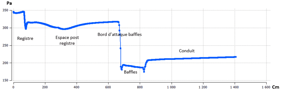
Calculation of pressure losses by CFD simulation and sizing of generator set fans
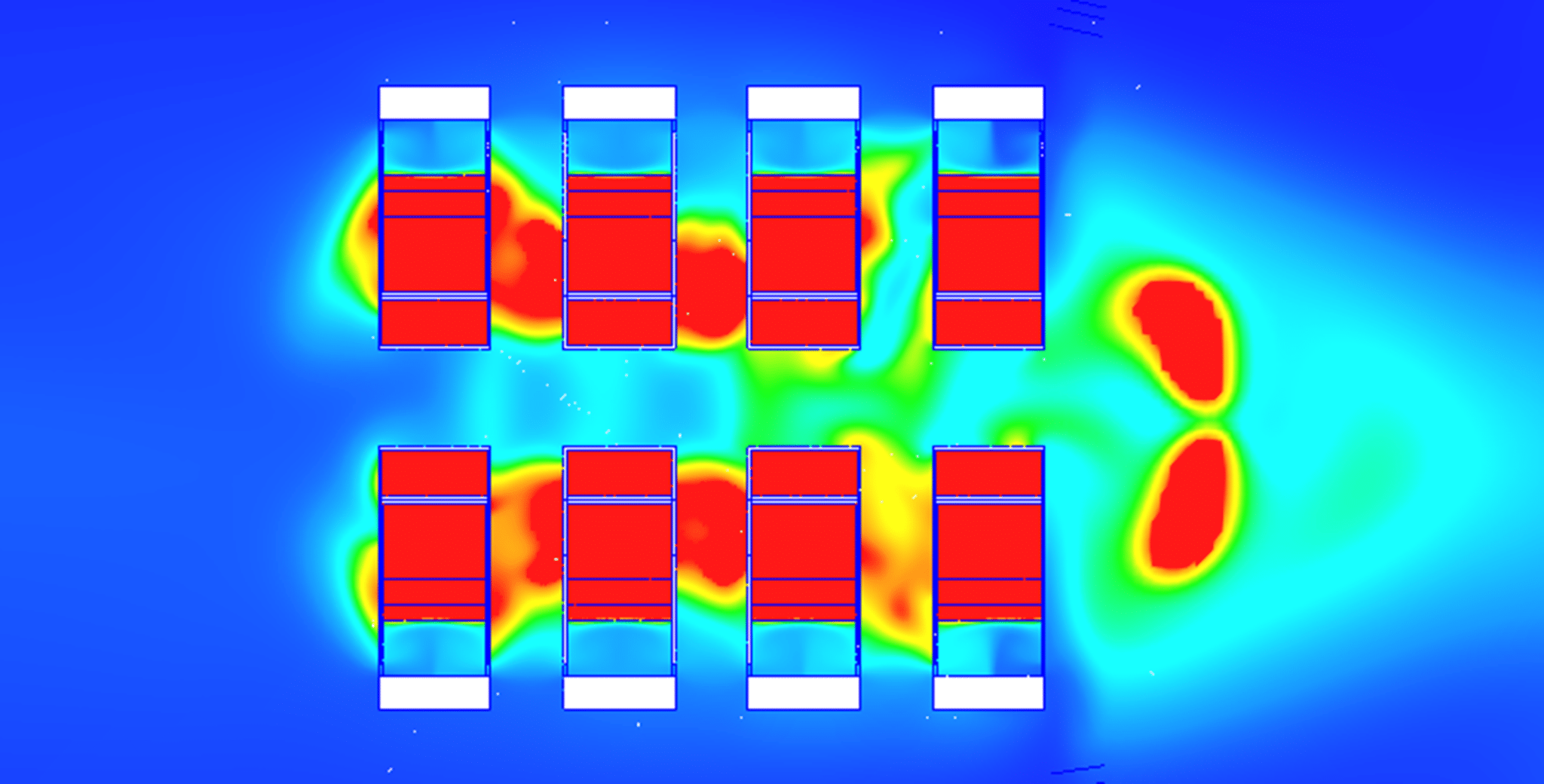
We carry out head loss studies for acoustic baffles and sizing of fans. As a function of air velocities, pressure drops become exponential. The different elements that disturb the fan flows are the presence of the diesel engine and the generator.
The louvers and acoustic baffles located near and upstream of the exhaust are a major source of pressure drop for the fans . Minor resistance to flow, on the other hand, comes from the battery banks, fuel tanks, intake pipes, and the engine’s exhaust stack.
In addition to the airflow within the generator room, another flow must be considered: the wind flow over the building. This is because wind can blow directly onto the generator room, potentially causing a greater pressure drop and, more importantly, recirculating superheated exhaust gases back towards the engine intake.
The louvers and acoustic baffles located near and upstream of the exhaust are a major source of pressure drop for fans. Minor resistance to flow, however, comes from the battery banks, fuel tanks, intake pipes and the engine’s exhaust chimney.
In addition to the airflow within the generator room, another flow must be considered: the wind flow over the building. This is because wind can blow directly onto the generator room, potentially causing a greater pressure drop and, more importantly, recirculating superheated exhaust gases back towards the engine intake.

CFD studies of pressure losses – Local generator group
Contamination of HVAC systems by diesel engine exhaust gases
We are studying the diffusion of NOx and other pollutants that can degrade the fresh air in offices
A generator is one of the best ways to cope with power outages. However, it’s a double-edged sword. It’s important to remember that the engine of this equipment releases pollutants to produce electricity. More specifically, these are carbon dioxide , sulfur dioxide , and nitrogen oxides . Generators generally run on gasoline, gas, or diesel. They can therefore significantly pollute the surrounding atmosphere , especially when used intensively during a power outage.
Our analyses may include monitoring the dispersion of exhaust gases.
We are studying the dissipation of pollutants from generator set emissions and we are verifying that there is no direct recirculation on my hygienic air extraction systems (AEA) of nearby premises.
CFD studies of plumes for an extreme scenario
Find out more: