Thermal-tank study
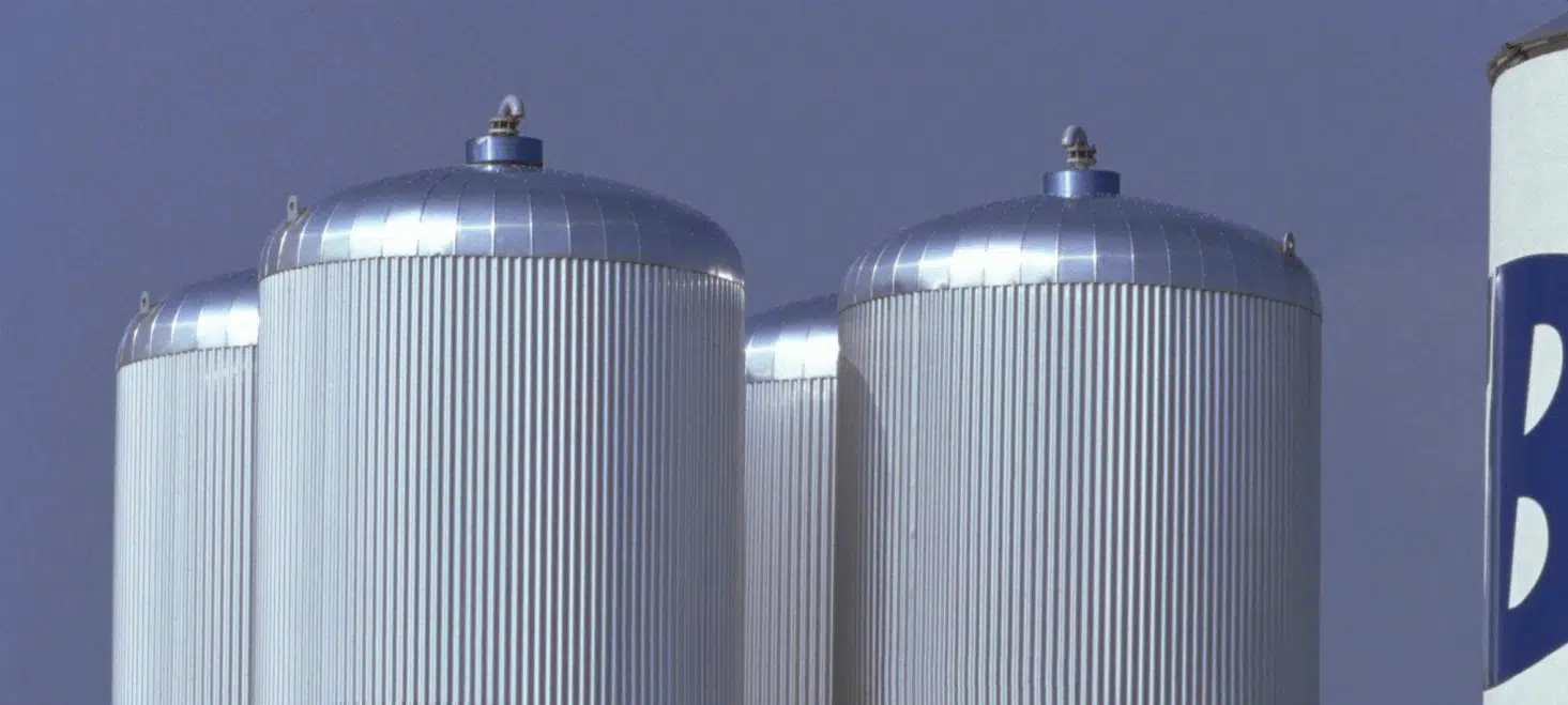
EOLIOS optimises thermal storage tanks: a buffer tank is a widely proven technology for storing heat energy (hot or cold) during off-peak hours.
Design
- Design, analysis, optimisation
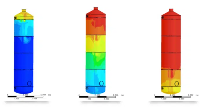
- Temperature distribution
- Thermocline thickness
Analyse
- Compartmentalisation study
- Transient study
- Laminar flow
Optimise
- Energy optimisation
- Heat-pump optimisation
- Pressure-loss calculation
Coupled with cooling systems (heat pump), this tank makes it possible to use the stored energy at peak hours, minimising consumption costs and smoothing peaks in power demand.
How thermal storage works
Water-based thermal storage
In a chilled-water storage system, thermal energy is stored as cold water in a stratified buffer tank containing both cold water and warm return water. During charging, the chilled water is pumped to the bottom of the tank while an equal amount of warm water is drawn off at the top; during discharging, the cold water is drawn off at the bottom and the warm water reintroduced at the top. A thermal stratification then occurs: the warm water (low density) stays at the top, the cold water (high density) settles at the bottom.
How to optimise a thermal storage tank?
Optimising the thermocline height
The thermocline is the transition region (temperature gradient) between the hot and cold zones; of low energy value, it moves from bottom to top during charging and the reverse during discharging. Its thickness represents the inefficiency of the tank: the more efficient the tank, the thinner the thermocline. Stratification depends on:
- the temperature loss to the environment by conduction (insulation);
- the tank design (height and diameter favouring stratification);
- the design of the inlet and outlet diffusers (laminar flow avoiding mixing);
- the physical compartmentalisation and the choice of specific diffusers.
Optimisation through CFD simulation
Through CFD simulation, EOLIOS supports the design of your tanks: mapping the temperature distribution, predicting the thermocline thickness optimised through testing, designing and optimising the number of compartments, visualising the flow throughout the tank, and predicting the temperature, velocity and pressure at every point and at every moment of the process.
Study of the temperature evolution of the water loop
To calculate the temperature evolution of a water loop at the tank outlet, several physical phenomena are taken into account:
- Tank energy balance: energy exchanged between the water and the tank (thermal capacity, losses, internal exchangers);
- Thermal losses: depending on the design, the insulation and the inside/outside temperature difference;
- Water flow rate in the loop: influenced by the exchanger power, the temperature difference and the hydraulic resistance;
- Heat exchange with the environment: gains or losses depending on the conditions (e.g. cold airflow).
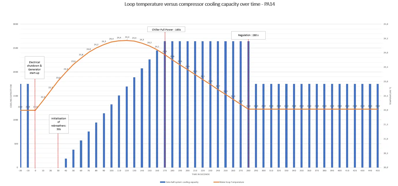
Depending on these factors and the dynamics of the loop, a mathematical model — often based on differential equations — calculates the evolution of the temperature over time.