Continue navigation :
Our latest news :
Our projects :


Our areas of expertise :
What is CFD simulation?
Blowing air into a room, removing smoke from a parking lot, cooling a data center, predicting the wind around a tower: these are all invisible phenomena that numerical fluid simulation now allows us to see, quantify and optimize.
Computational Fluid Dynamics (CFD) simulations
Computational Fluid Dynamics ( CFD ), or computational fluid dynamics , is the discipline of simulating the flow of fluids—air, water, smoke, gas—on a computer, along with the accompanying heat and mass transfers. Where models were once built in wind tunnels, CFD reproduces these phenomena in a true virtual laboratory, faithful to the laws of physics.
The behavior of a fluid is governed by the Navier-Stokes equations , a set of equations that describe how velocity, pressure, and temperature change at every point in space. These equations are remarkably elegant… and impossible to solve manually in almost all real-world cases. This is where numerical computation comes in.


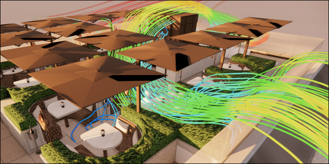
Visuals of CFD results (streamlines, wall pressure, temperature isosurfaces)
The fundamental idea behind CFD is easy to grasp. Imagine a pointillist mural: from a distance, it’s a continuous image; up close, it’s thousands of tiny dots placed side by side. CFD works in the same way. It divides the volume of data under study—a room, a district, a heat exchanger—into millions of minuscule cells , then solves the equations of physics within each one. When these cells are placed end to end, they reconstruct the complete flow, with a realism impossible to achieve through intuition or manual calculation.
At Eolios , this discipline is our core business. We harness the power of simulation for your projects, from buildings to industrial sites, to transform complex questions—”Will this room be comfortable?”, “Will the smoke be evacuated in time?”, “Will my system overheat?”—into quantifiable, visual, and reliable answers.
Why conduct a CFD study?
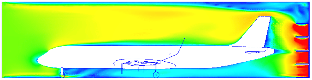
CFD: A digital alternative to the wind tunnel
Like a digital wind tunnel, a CFD study serves a clear purpose: to understand and predict the behavior of a fluid before construction , and therefore before incurring irreversible costs. It allows verification that a design will achieve its objectives—comfort, safety, energy efficiency, regulatory compliance—and, if not, to precisely identify why and how to remedy the situation.
In practical terms, a CFD study is used to determine the required ventilation capacity (what ventilation power? what wind pressure?), to validate the system (does the smoke extraction system meet the fire scenario requirements?), to optimize the system (can energy consumption be reduced without compromising comfort?), and to provide justification (provide quantified evidence to project owners and authorities). It is both a decision-making tool and an engineering tool.
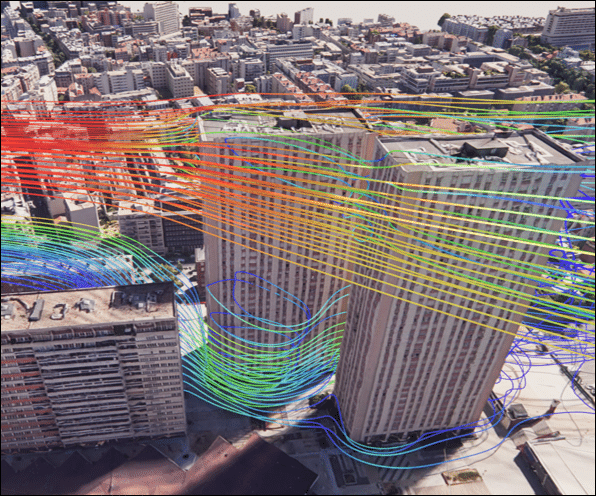
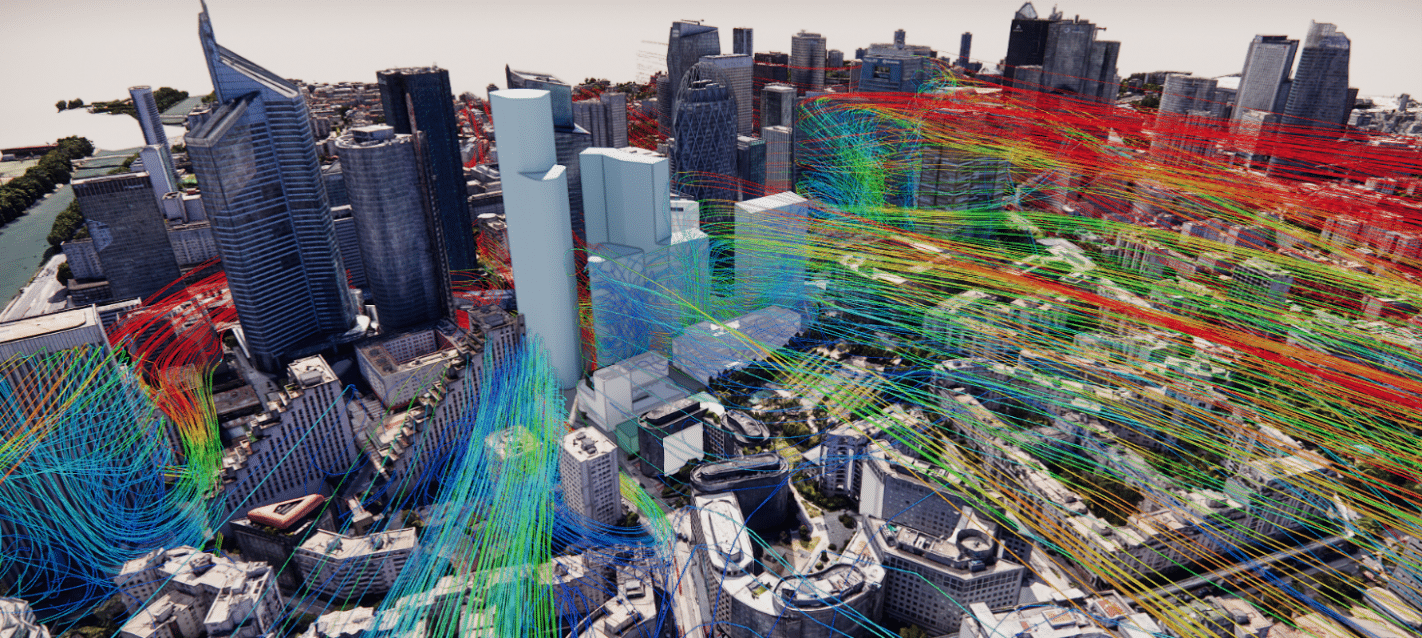
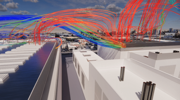
LES simulation of wind at the neighborhood scale
Cost and time savings from a CFD study
Building a prototype, instrumenting a model in a wind tunnel, or modifying an existing structure is expensive—and the later the cost is realized, the more expensive it becomes. CFD reverses this logic: you test, you make mistakes, and you correct them in the virtual world, where an error costs only a few hours of computation.
A single digital model allows for the exploration of dozens of variations : moving a supply vent, changing its orientation, adding an extractor fan, simulating a heatwave or a windless day. Each scenario that would have required a new physical model becomes a simple iteration. The marginal cost of an additional test plummets, and design decisions are based on data rather than assumptions.
The most valuable time savings occur upstream: detecting a design flaw at the planning stage avoids a rework that would cost months and hundreds of thousands of euros. Simulation acts as insurance: a controlled investment to eliminate a major risk.
Cost and time savings from a CFD study
Seeing the invisible. Air, heat, and smoke are invisible to the naked eye. CFD (Computational Fluid Dynamics) gives them color, shape, and movement: we observe heat accumulating under a skylight, cold air “falling” from a poorly positioned vent, a vortex forming behind an obstacle. This intuitive interpretation of a complex phenomenon is a powerful argument for persuasion, both in design meetings and safety committees.
Adapt the model as desired. A CFD model is dynamic: you modify a parameter, rerun it, and compare. Geometry, flow rates, outside temperatures, room occupancy—everything is adjustable. It’s like a wind tunnel where you can change the conditions with a simple click, without dismantling anything.
An alternative — and a complement — to the experimental approach. Some measurements are impossible, dangerous, or prohibitively expensive: instrumenting every cubic meter of an industrial building, triggering a real fire to test smoke extraction, or measuring wind speed at the top of a tower that doesn’t yet exist. CFD provides access to these inaccessible points, anywhere and at any time, without risk. When compared with real-world measurements, it gains even more credibility: simulation and experimentation reinforce each other.
How a CFD study works
3D modeling
It all begins with the construction of a three-dimensional digital model: the “setting” in which the fluid will circulate. From your plans, BIM files or surveys, we reconstruct the geometry of the area studied — a room, an entire building, a district or a piece of equipment — keeping only what actually influences the flow.
This step is a delicate art: too much detail unnecessarily complicates the calculation, while too little compromises its accuracy. The key is to simplify intelligently, retaining the essential elements (obstacles, openings, heat sources) and eliminating the superfluous.
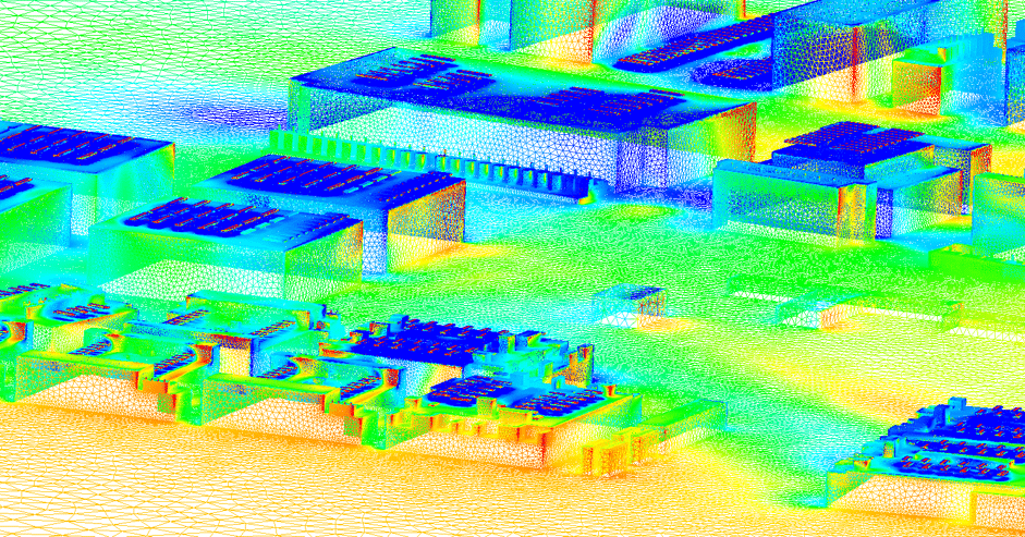
Finite element meshing
The 3D model is then divided into a mesh : an assembly of millions of small cells on which the equations will be solved. This is the invisible framework of any simulation, and probably the most crucial step for the quality of the result.
The mesh can be visualized as a construction set of building blocks: for a large flat surface, large blocks are sufficient; but to accurately reproduce a curve or a fine angle, tiny blocks are needed. In CFD, the mesh is therefore refined where “important things are happening” for the fluid—near walls, supply vents, and areas of high gradient—and simplified where the flow is calm. This balance between accuracy and computational cost makes all the difference between a robust simulation and a misleading result .
Boundary conditions
Boundary conditions describe what happens at the boundaries of the domain — flow rate and temperature of incoming air, power released by servers or occupants, behavior of walls, openings to the outside, wind speed and direction… Fair and representative boundary conditions are the guarantee of a usable result; this is where the engineer’s experience is irreplaceable, because it is necessary to translate a real situation — often uncertain — into rigorous input data.
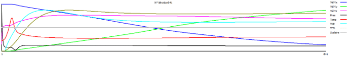
The resolution model
Then comes the actual calculation. The solver applies the equations of fluid mechanics to each cell of the mesh , then repeats the operation again and again until the solution stabilizes: this is called convergence. A simulation can thus require computing resources for hours, or even days, to reach a consistent equilibrium state.
A crucial choice concerns the modeling of turbulence—those chaotic eddies that make flows so difficult to predict. Depending on the required accuracy and the computational budget, one will choose either an averaged and economical approach ( RANS models) or a more refined approach that captures unsteady structures ( LES models).

Comparison – RANS Model vs. LES Model – Steelworks
The experimental comparison of the results
A simulation is only valuable if it can be relied upon. That’s why, when relevant, we compare our numerical results with real-world measurements : on-site air velocity and temperature measurement campaigns, smoke tests, and sensor monitoring. This validation step completes the process: it confirms that the model accurately reproduces reality, and therefore that its predictions are trustworthy.

Comparison – LES Model vs. RANS Model - Steelworks
Far from being opposed, simulation and fieldwork form a duo: experimentation calibrates and validates the model, while the model generalizes and explains the experimentation . It is this rigor that distinguishes an engineering study from a simple computer-generated image.
The results of a CFD study
Average, point, and curve values
Closely aligned with sizing needs, CFD provides quantifiable values : average room temperature, air velocity at a specific point, flow rate through an opening, pressure difference, and comfort indices. These values can be plotted as curves—temperature evolution along a data center aisle, velocity profile at head height—which can be directly compared to regulatory or contractual requirements.

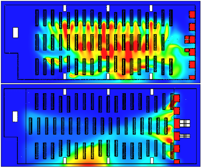
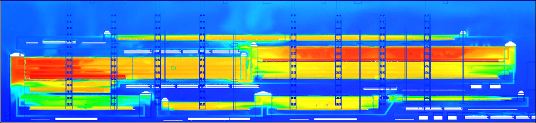
Plans and sections
By virtually “slicing” the domain along a plane, colored cross-sections are obtained that reveal the distribution of a quantity—temperature, velocity, concentration— like an X-ray of the flow. These planes are the most immediate reading tool: at a glance, one can identify an area that is too hot, a troublesome air current, or a pocket of stagnant air.
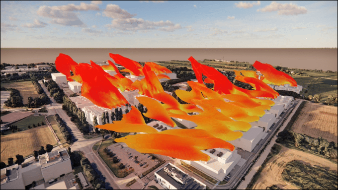
3D visualization: isosurfaces and streamlines
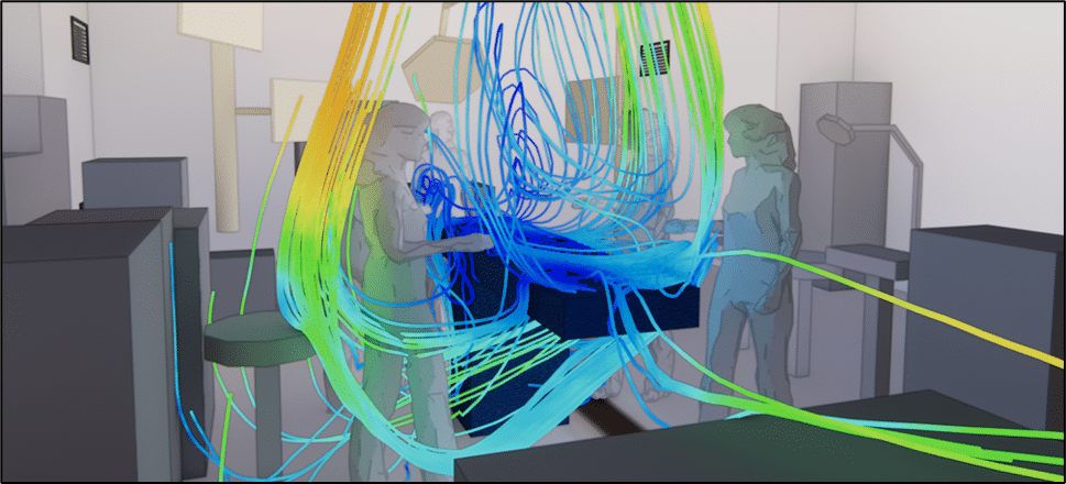
The third dimension gives CFD its full power. Streamlines follow the path of the air like colored ribbons, revealing vortices, air short circuits, and preferential paths. Isosurfaces , for their part, envelop all regions sharing the same value—for example, the “bubble” of air exceeding a critical temperature—and materialize in space what would otherwise remain abstract.
The interim results
Not all phenomena are static. The deployment of a plume of smoke, the temperature rise after an air conditioning failure, a gust of wind: these are transient phenomena that evolve second by second. Unsteady CFD captures this dynamic and presents it in the form of animations, where the scenario unfolds like a film—a crucial advantage for safety and smoke extraction studies.
Transient studies - Rupture of reservoir and thermal storage tank
Post-study support
A CFD study doesn’t end with the delivery of images. We translate the results into concrete and prioritized recommendations , write clear reports , and support you in defending your choices with project owners, inspection bodies, and safety commissions. If necessary, we adapt the model throughout the project, ensuring it remains a useful decision-making tool throughout the design and operation phases.
At EOLIOS , simulation is a starting point, not an end in itself: our added value lies as much in the rigor of the calculation as in the quality of the advice that surrounds it.
In which areas do we conduct CFD studies?
Air and wind
At the scale of a building or a neighborhood, wind shapes comfort, safety, and quality of life. We model atmospheric flows to assess pedestrian comfort, calculate pressures exerted on facades, anticipate extreme gusts on exposed structures, and monitor the dispersion of pollutants, dust, and odors in the urban environment.
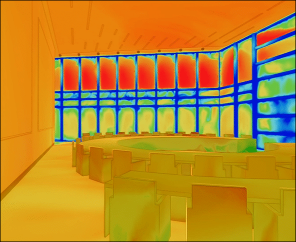
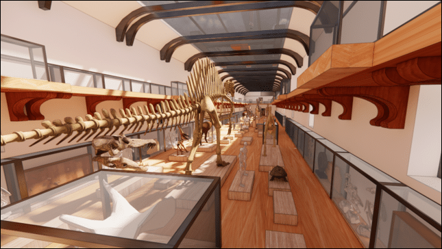
HVAC engineering
Thermal comfort and indoor air quality are central to HVAC engineering. We simulate air behavior in a wide variety of spaces—offices, lobbies, atriums, skylights, high-ceilinged buildings, swimming pools, subway stations, and museums—to ensure a healthy and pleasant environment while controlling energy consumption. Computational Fluid Dynamics (CFD) supports Dynamic Thermal Simulation studies to address phenomena that global approaches cannot capture.

Industry
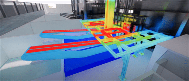
Industrial sites present demanding thermal and aerodynamic challenges: intense heat, dust, gases, and fluid networks under stress. We support manufacturers with natural ventilation of their workshops, dust and powder dispersion, cooling of electrical equipment, chimney sizing, and risks related to networks and storage — all the way to the creation of digital process twins (glassworks, steelworks, aluminum plants, etc.).
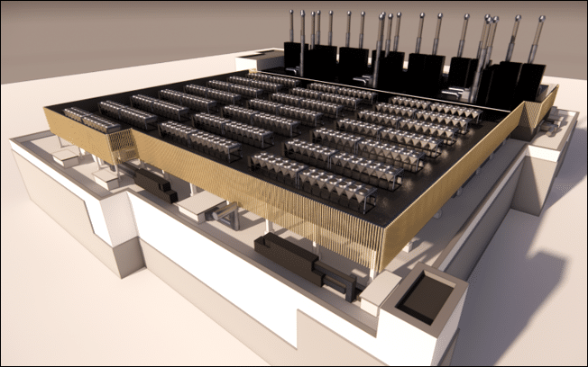
Data center
Cooling increasingly dense servers without wasting energy is one of the major challenges of the digital age. CFD has become essential for designing, auditing, and optimizing data centers: controlling airflow in rooms, eliminating hot spots, calculating and improving PUE, studying external thermal impacts, preparing load banks for commissioning, and creating a digital twin to manage daily operations.
Laboratories
In laboratories and cleanrooms, air quality control is essential for personnel safety and process reliability. We assess fume hoods, audit cleanroom airflow, and study dust control and contaminant propagation to guarantee compliance with cleanliness classes and operator protection.
Smoke control
In the event of a fire, a few minutes can make all the difference. Fire Detection and Calculation (FDC) allows us to simulate smoke propagation and verify that occupants have sufficient time and escape routes for a safe evacuation. We design and validate smoke extraction systems, model evacuation routes, and support fire safety engineering from the initial regulatory scenario to the safety commission.
Smoke extraction studies for a restaurant
A project, a question, a doubt?
Whatever the complexity of your fluid or thermal challenge, the EOLIOS teams are there to help you transform it into a clear, quantified, and visual solution. Contact us to discuss your project.
Examples of CFD simulation applications
Example of CFD simulation projects :

CFD simulation of the aerodynamic phenomena of a peloton of cyclists

Thermal draft effect

Pedestrian comfort criteria and mapping

Impact of wind on a solar power plant

CFD simulation of drag: advanced calculation to improve aerodynamics

Pressure loss and hydraulic resistance

Legionnaires’ disease and cooling towers

CFD study of extreme wind conditions on solar panels and power plants

CFD simulation: An alternative to wind tunnel testing