
The thermal challenges of electronics
As components shrink and their power density rises, heat becomes the primary limiting factor for performance and reliability.
The power of processors (CPUs) and accelerators (GPUs) keeps rising, driven by high-performance computing and artificial intelligence. Extracting that heat from ever more constrained spaces while guaranteeing a long service life is a central challenge of product development. Thermal management is no longer an end-of-project check: it is a pillar of design, to be addressed as early as possible.
What makes cooling critical
- Miniaturisation. The same heat, or more, has to be removed from a smaller surface: local heat fluxes soar.
- Power density. A modern compute component can dissipate several hundred watts over a few square centimetres.
- Reliability and service life. Component endurance depends directly on their operating temperature.
- Environmental constraints. Ambient temperature, altitude, humidity and sometimes a ban on fans impose narrow margins.
A siloed approach, where each discipline optimises its own part, leads to costly fixes late in the cycle. Early coordination between electronics designers, mechanical and thermal engineers, by contrast, builds thermal constraints into the very first architecture choices.
Heat, the leading cause of electronics failure
A prolonged rise in temperature accelerates semiconductor ageing. As an order of magnitude, every 10 °C increase can halve a component's service life: controlling thermal behaviour extends reliability.
The physics of electronics cooling
Cooling a component means organising the path heat follows from the junction of the semiconductor, where it is produced, to the air or fluid that carries it away. Three mechanisms combine along that path.
Conduction
- Transfer through solids: chip, thermal interface, package, heat-sink base. The first link, and often the limiting one.
Convection
- Removal by a fluid (air or liquid), natural or forced by a fan or pump: the mode most called upon in electronics.
Radiation
- Exchange infrared between surfaces: secondary in forced convection, it matters for fanless systems.
The thermal resistance (Rth, in °C/W) measures how hard it is for heat to flow along a path. The lower it is, the better heat escapes. It adds up along the chain, from junction to ambient, like electrical resistances in series.
The quantity that governs reliability is the junction temperature (Tj), at the heart of the component. Each manufacturer sets a maximum value not to be exceeded. It follows simply from the dissipated power and the thermal resistance of the path:
A hot spot (hot spot) is a localised area where the temperature clearly exceeds its surroundings: a poorly ventilated component, recirculated air, an obstacle in the flow. This is where reliability drifts begin, and precisely what CFD is used to locate.
When the temperature climbs anyway, components protect themselves by lowering their clock frequency: this is throttling (thermal throttling), a direct performance loss. Thermal sizing therefore targets reliability as much as sustained nominal performance.
From component to equipment
Electronics cooling is addressed at several nested scales. A complete CFD study links them, because a choice made at one level conditions the next.
The chip
- Junction, package and thermal interface (TIM): the very first resistance segment, and often the most penalising.
The board (PCB)
- Copper traces and planes, thermal vias and component placement: the printed circuit board actively spreads the heat.
The equipment
- Enclosure, ventilation and heat sinks: the way the airflow is organised decides the temperature each component sees.
At board level, several levers are decided very early: choosing less dissipative components where possible, increasing trace cross-sections, dedicating copper layers to heat spreading, and above all strategically placing the hottest components so that they do not heat one another or sit in air that is already warm.
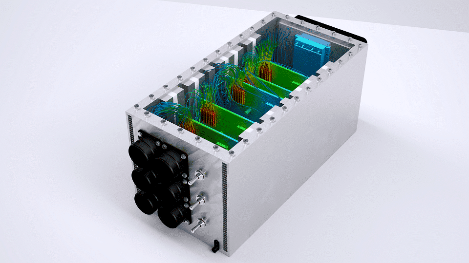
At equipment level, the issue becomes one of airflow management: where cool air enters, how it travels between the boards, where it leaves. A badly placed inlet, an over-restrictive grille or an undersized fan is enough to create stagnant air zones, and therefore hot spots, even with good heat sinks.
Cooling levers
Solutions fall into two complementary families: devices that are passive, improving conduction and exchange with no added energy, and devices that are active, forcing a fluid to circulate.
Passive solutions
- Finned heat sinks to increase the exchange surface.
- Heat pipes and vapour chambers to move heat towards a more favourable area.
- Thermal interfaces (TIM) and copper planes to lower the conduction resistance.
Active solutions
- Forced ventilation (air convection) for common densities.
- Liquid cold plates (direct-to-chip) in contact with the critical components.
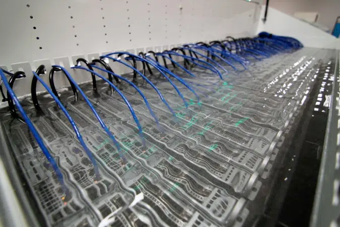
- Dielectric immersion for very high densities, with no fan.
Moving from air to liquid is justified when power density exceeds what air convection can reasonably remove. Liquid cooling offers far higher thermal efficiency and makes the recovered heat usable, at the price of higher investment and maintenance, and of vigilance over leak-tightness.
| Solution | Thermal capacity | Complexity / cost | Noise | Typical use case |
|---|---|---|---|---|
| Natural convection | Low | Very low | None | Telecom, sealed embedded systems, low powers |
| Forced ventilation (air) | Moderate | Low | Present | The majority of equipment and servers |
| Heat pipes / vapour chamber | Good — heat transport | Moderate | Depends on ventilation | Laptops, compact boards, GPUs |
| Liquid cold plate (direct-to-chip) | High | High | Low | High-performance computing, AI, high density |
| Dielectric immersion | Optimal | High | None | Extreme densities, recoverable heat |
Fields of application
Electronics cooling reaches far beyond server rooms: anywhere a component dissipates heat in a constrained volume.
Computing & AI
- CPUs and high-density GPUs: AI and HPC are pushing towards direct-to-chip liquid cooling.
Power electronics
- Inverters and electric-vehicle charging stations: high currents and new thermal constraints.
Telecom & embedded
- Equipment in harsh environments, often fanless: natural convection has to be enough.
In each of these cases, simulation makes it possible to explore a large number of scenarios (placement, heat sinks, flow rates, load regimes) without multiplying physical prototypes, and to converge on a cooling solution that is both reliable and frugal.
Learn more: data center engineeringThe EOLIOS CFD method
EOLIOS puts computational fluid dynamics to work for electronics cooling, from the component to the complete equipment. The approach starts from the real geometry and renders temperature fields and airflows in 3D, so that design decisions rest on quantified data.
The course of a study
- CAD import and simplification: only what matters thermally is kept.
- Modelling of every transfer mode: conduction, convection, radiation and liquid cooling.
- Mesh refined around the critical components (heat sinks, fins, interfaces).
- Steady-state or transient computation, including load scenarios and fan-failure cases.
The simulation identifies hot spots, quantifies the margins against the maximum junction temperature and compares several variants: component placement, heat-sink choice, ventilation flow rate, switching to liquid. Every gain is quantified before manufacturing.
What we deliver
- 3D maps of temperature and air velocity.
- Margins on junction temperature, component by component.
- Quantified comparison of cooling variants.
- Recommendations on placement, heat dissipation and ventilation.