
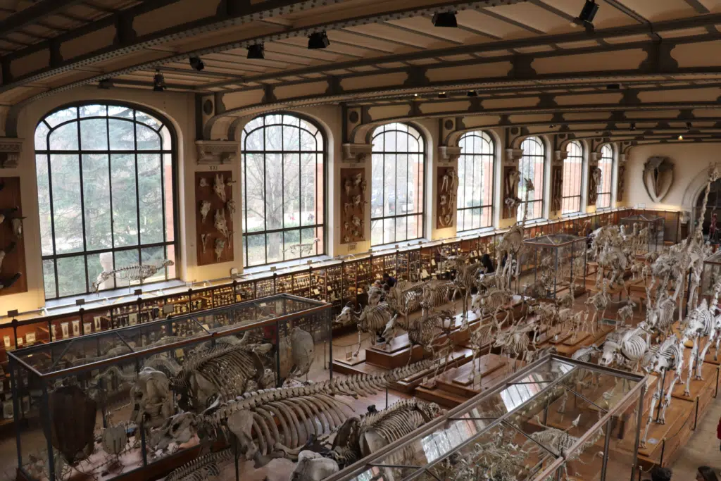
Thermo-airflow optimisation of the Gallery of Palaeontology at the French National Museum of Natural History: visitor comfort, collection conservation and respect for the heritage.
EOLIOS's expertise in CFD simulation (Computational Fluid Dynamics) and indoor-environment optimisation played a key role in analysing and improving the airflow comfort of the Gallery of Palaeontology at the French National Museum of Natural History. Our know-how made it possible to precisely characterise the thermo-airflow behaviours of this exceptional heritage volume and to propose concrete optimisation solutions, reconciling occupant comfort, collection conservation and respect for the architectural constraints.
The essentials. The Gallery of Palaeontology at the MNHN is an exceptional heritage volume: great heights, glass roofs and open levels from the garden level to the roof. EOLIOS built a 3D CFD model of nearly 50 million elements, calibrated against a field audit (in-situ measurements, smoke tests) down to a residual criterion < 10⁻⁴. Two scenarios, summer and winter, reveal the thermal stratification and the zones where velocity exceeds 0.4 m/s or temperature leaves 18–25 °C. The outcome: concrete levers — intermediate diffusion, adjustable-orientation nozzles, upper-part sweeping, attendance-based control — serving comfort, collection conservation and respect for the listed façades.
EOLIOS is a reference in CFD simulation applied to heritage buildings and major cultural facilities. Our studies draw on experience from real-condition measurement campaigns and recognised expertise in modelling complex volumes with high thermal stakes.
Cultural and heritage buildings present a particular challenge for airflow comfort. The Gallery of Palaeontology perfectly illustrates this reality with its great ceiling heights, its volumes open over several levels and its large glazed surfaces.
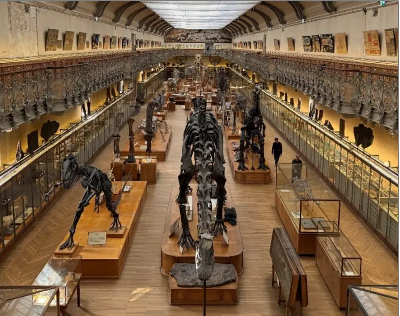
These characteristics generate phenomena amplified compared with standard buildings, notably a marked thermal stratification where warm air accumulates at height, creating differences of several degrees over the vertical. This mechanism stems from the thermal draught effect. Added to this are strong heritage constraints, since the listed façades limit possible interventions on the envelope, as well as a dual, variable occupancy between fluctuating public and permanent staff whose requirements differ.
The imperatives of collection conservation finally add to human comfort, requiring stability of the ambient conditions. These particularities make airflow comfort in this type of building a complex engineering problem, where empirical approaches quickly reach their limits.
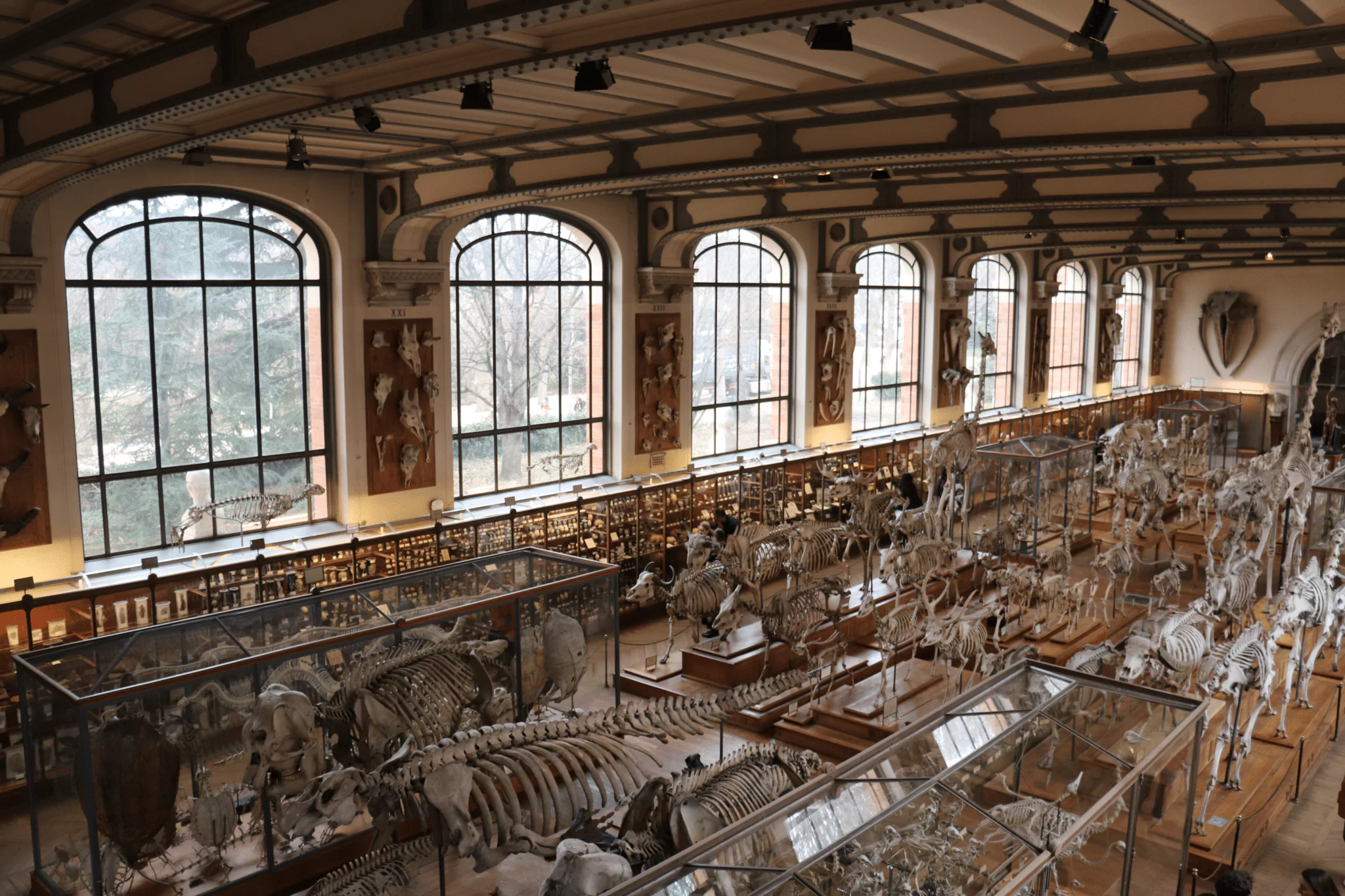
Stratification is the formation of air layers at different temperatures according to height: warm air, being less dense, rises and accumulates in the upper part, while cooler air stays at floor level. In a large volume like the Gallery, the difference can reach several degrees between the occupied zone and the vault.
A conservation issue. Beyond human comfort, the collections require stability of the ambient conditions. Temperature and humidity variations, amplified by stratification and by the solar gains of the glass roofs, stress sensitive materials: mastering the airflow also means protecting the exhibited heritage.
Faced with this complexity, resorting to CFD appears as the most suitable tool, for several complementary reasons. Unlike simplified methods that compute global flow rates without representing the local physical reality, CFD offers a complete three-dimensional view making it possible to visualise precisely the trajectory of the air streams, the recirculation zones and the temperature gradients, thereby identifying the critical discomfort points that escape global approaches.
CFD, or computational fluid dynamics, solves the equations of air flow (velocity, pressure, temperature) on a 3D mesh of the studied volume. It restores, at every point, the velocity and temperature fields, where global methods provide only averages.
Beyond this three-dimensional view, CFD combines three decisive strengths :
Test multiple scenarios risk-free — existing/planned, geometry, control parameters — with no material cost or disruption to operations, and avoid costly design errors that would otherwise be corrected afterwards.
Natively integrate the thermal couplings between solar radiation, conduction and convection, essential to assess the comfort actually felt by occupants.
Communicate and decide thanks to colour visualisations, a shared support between the project stakeholders. At the design stage, CFD becomes an indispensable prerequisite for any intervention on the ventilation.
CFD simulation is not limited to analysing existing airflows: it is above all a comfort-optimisation tool. By precisely modelling the conditions felt by occupants (air velocity, ambient temperature, thermal stratification), it makes it possible to identify the discomfort zones and to test corrective solutions before any works commitment. In spaces open to the public like the Gallery of Palaeontology, where occasional visitors and permanent staff coexist, this ability to anticipate and refine the ambient conditions is a decisive asset to steer design choices toward solutions that are both high-performing and durable.
Learn more: CFD in comfort analysisThe CFD study carried out by EOLIOS on the Gallery of Palaeontology is built around three complementary objectives.
Understand the thermo-airflow phenomena, in existing as in planned configuration: velocity and temperature fields, dominant transfer mechanisms and interactions between the building's levels.
Analyse the effectiveness of the ventilation system: supply / extract balance, absence of short-circuiting, actual air-change rates and energy efficiency of the simulated configurations.
Identify the discomfort risks: map the zones where velocity exceeds 0.4 m/s or temperature leaves 18–25 °C, then prioritise the intervention priorities according to impact and feasibility.
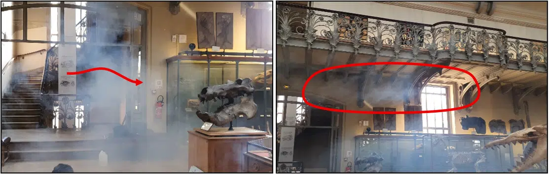
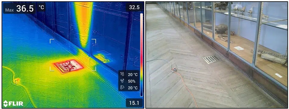
An in-depth audit was conducted directly within the Gallery of Palaeontology to precisely characterise the thermo-airflow phenomena in real operating conditions. Measurement campaigns were carried out across all levels to quantify air velocities, temperatures and flow rates at the ventilation system terminals, providing a reliable and representative initial state of the installation's operation. Qualitative visualisations of the airflow trajectories were also conducted to identify the recirculation zones, the parasitic currents and the malfunctions of the existing diffusion devices.
Beyond data collection, this on-site audit is a key step to grasp the real behaviour of the building in its heritage environment, often complex and constrained. It makes it possible to confront the theoretical schematics and existing HVAC drawings with the reality of the field, to integrate the effects of operating practices, architectural constraints, weather conditions and actual space uses, all elements rarely fully documented in the technical files.
This fine knowledge of the site is essential to avoid simplifying modelling assumptions far removed from real operation. The field observations from the audit thus formed an essential basis to feed, calibrate and validate the CFD numerical model. They guarantee consistency between simulation and real behaviour, strengthening the reliability of the results and the relevance of the proposed solutions. The audit therefore appears as an essential prerequisite for any lasting analysis and optimisation of the airflow-comfort issues in this exceptional heritage.
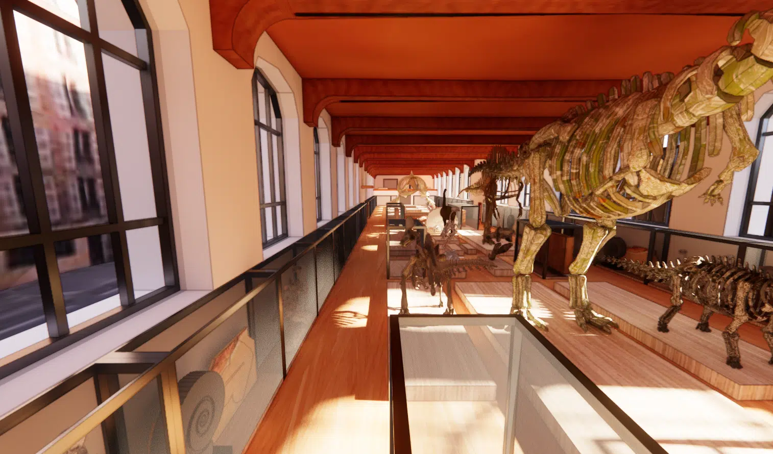
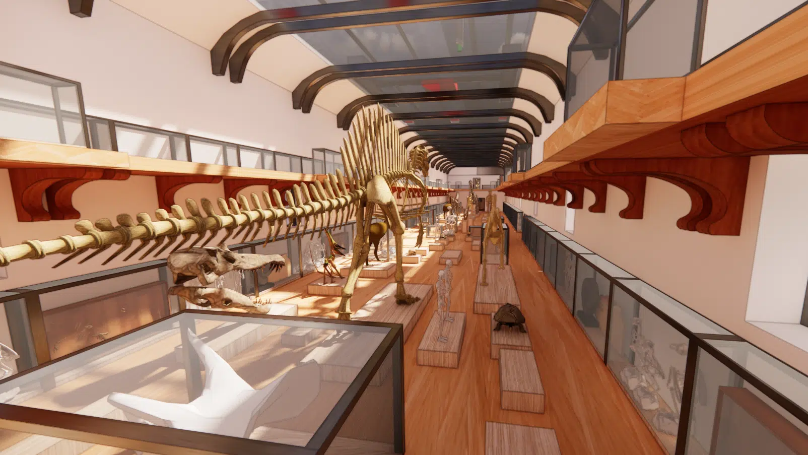
The 3D CFD modelling developed by EOLIOS rests on a rigorous geometric base, built from the existing execution drawings supplemented by the surveys and observations made during the on-site audit. This step is decisive: the quality and representativeness of the model directly condition the relevance of the results obtained.
On the basis of the collected data, EOLIOS developed a detailed model integrating the complete geometry of the Gallery of Palaeontology across all its levels (from the garden level to the roof) as well as all the equipment influencing the site's airflow: air-handling units and their distribution network, supply and extract grilles, internal and solar heat sources, but also all the architectural elements guiding the flows such as the display cases, the partitions and the walkway guardrails.
The level of geometric detail is chosen with care to faithfully represent the elements having a significant influence on the velocity and temperature fields, while rationalising the secondary details. With a mesh of about 50 million fluid elements, this balance between accuracy and simplification guarantees the numerical robustness of the simulations and results directly usable for analysis and decision support.
In practice, the CFD approach follows an iterative process structured into successive steps :
Build the geometric model from the execution drawings and audit surveys.
Define the boundary conditions and the thermo-physical properties.
Solve numerically, then analyse in detail the flow and temperature fields.
Calibrate against the field measurements before engaging the improvement iterations.
The calibration phase is a key step of the CFD approach: it guarantees consistency between the simulation results and the real behaviour of the system. Concretely, it means adjusting the boundary conditions and the modelling assumptions (supply and extract flow rates, surface temperatures of walls and cases, weather conditions, solar gains, internal heat sources linked to occupancy and equipment) to obtain a satisfactory match between the computed quantities and the measurements taken in situ during the audit.
Once the model is calibrated and validated, with convergence attested by a residual criterion below 10⁻⁴, it becomes a reliable predictive tool to study the impact of various modifications (flow-rate changes, diffuser geometry, ventilation system configuration) and to analyse the new flow and thermal-distribution dynamics in support of technical decision-making.
The CFD numerical simulation makes it possible to virtually reproduce the behaviour of the air inside the Gallery of Palaeontology under realistic conditions, without having to wait for the relevant seasons or to carry out costly, lengthy in-situ measurements. By defining representative boundary conditions from the weather data of the nearest station (outdoor temperatures, solar exposure, ventilation system operation), it is possible to explore the building's behaviour in situations as varied as the summer heatwave or the deep winter cold.
Two critical scenarios were studied to frame the gallery's real operating range :
The winter scenario, corresponding to the coldest outdoor conditions, checks that the heating-by-ventilation system maintains a comfortable environment for visitors and staff, while limiting the energy waste linked to excessive stratification of warm air at height.
The summer scenario, representative of periods of intense heat, assesses the ability of the cooling system to cope with the significant solar gains entering through the glass roofs and windows, and to guarantee bearable conditions despite the high thermal load.
This dual approach gives the client a complete view of the expected performance, highlighting not only the average behaviours but also the potentially unfavourable situations to be treated as a priority.
The simulations produce three-dimensional maps of the studied physical quantities (air velocity, temperature) that make it possible to visually locate the compliant zones and those presenting discomfort risks. These representations, in the form of coloured isosurfaces or section planes, are a direct communication tool between engineers and decision-makers.
The analysis of the velocity fields reveals a heterogeneity of the flows according to the levels and zones considered. Overall, low velocities are observed in the gallery's large volumes, conducive to a calm, stable environment, but a few singular zones where the acceleration of the air creates risks of perceptible draughts.
In the summer period, a particular dynamic appears: the cold air injected at floor level tends to spread in a layer before rising along the walls, creating ascending currents that are sometimes troublesome right at the supply grilles. This phenomenon, typical of air-conditioned volumes with low-level supply, contrasts with the winter behaviour where warm air rises naturally and more homogeneously.
Worth remembering. Low-level supply, rather favourable in winter, reverses in summer: the grazing cold air rises along the walls and generates ascending currents near the grilles. This is exactly the kind of local phenomenon that simulation makes it possible to locate — and correct — before works.
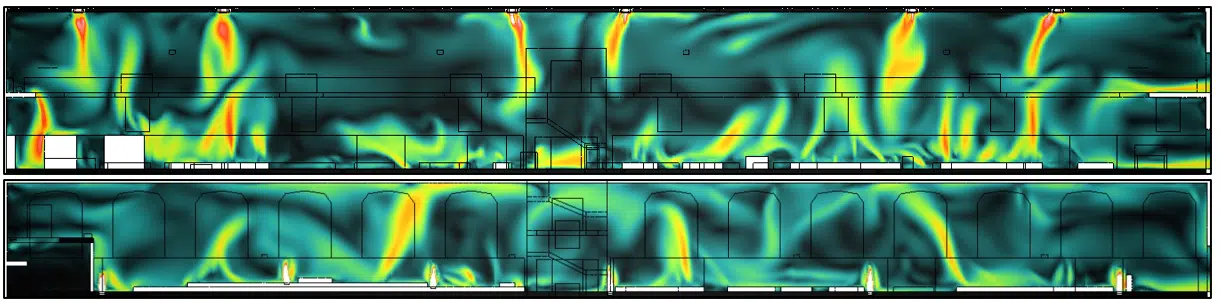
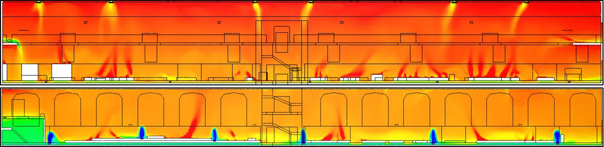
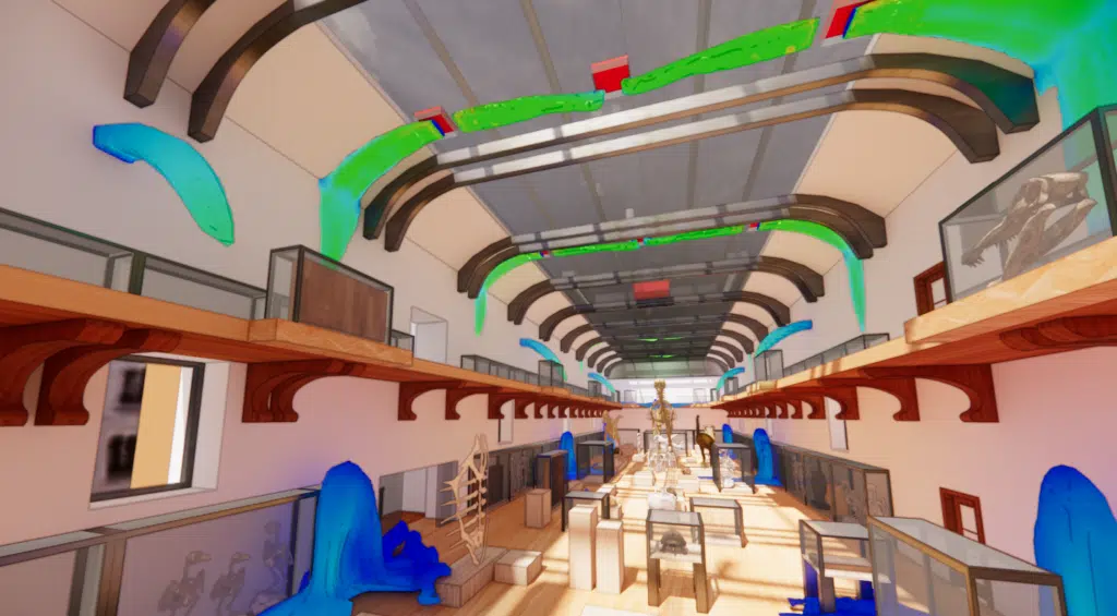
In winter, thermal stratification works rather in favour of comfort: warm air accumulates in the upper part (under the vault and roof) while the occupied zone stays in a temperate environment. The planned configuration reduces this vertical difference compared with the existing state, improving energy efficiency and comfort uniformity.
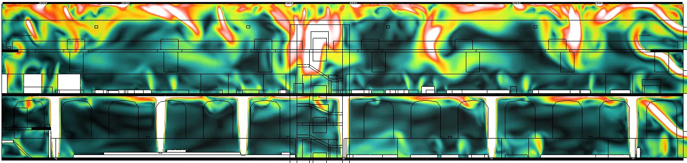
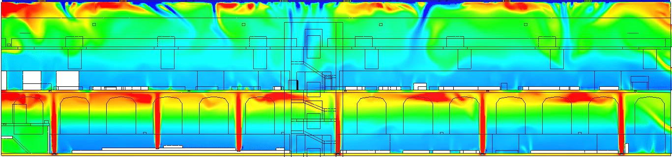
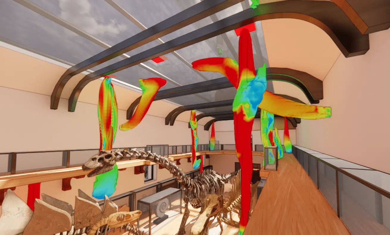
The comparison of the two scenarios gives an overall positive assessment of the configuration: while the winter operation appears satisfactory with well-controlled comfort conditions across all levels, the summer scenario reveals certain limits linked to the building's thermal inertia and the importance of its glazed surfaces. These findings, objectively highlighted by the simulation, justify the complementary optimisation proposals set out in the following section.
The simulations made it possible to identify several concrete optimisation levers to improve the thermo-airflow comfort of the Gallery of Palaeontology.
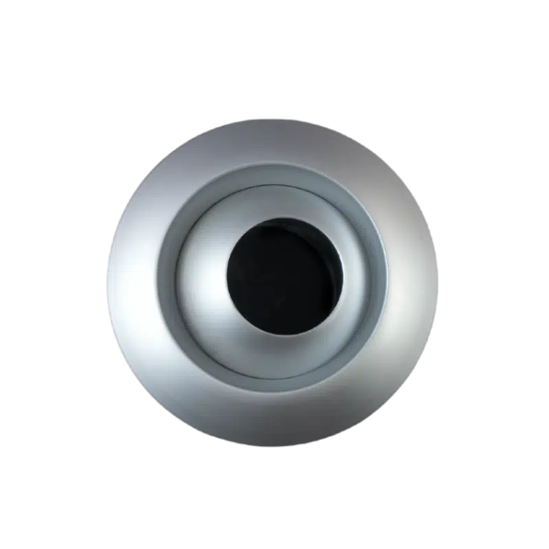
Installing intermediate diffusion elements allows a more uniform distribution of the airflows before they reach the occupied spaces, limiting the discomfort zones linked to excessive air velocities.
Replacing the existing diffusion equipment with adjustable-orientation models brings seasonal flexibility, making it possible to finely adapt the air distribution to the outdoor conditions.
The significant ceiling height and the communication between the gallery's levels led to recommending a controlled sweep of the upper parts of the volumes. This principle, which promotes the mixing of air layers without disturbing the occupied zone, proves particularly effective in mid-season, when assisted natural ventilation may be enough to maintain satisfactory comfort conditions.
Finally, a ventilation flow-rate control indexed on the museum's actual attendance optimises the balance between perceived comfort and energy consumption, avoiding both under-sizing and over-ventilation that generates parasitic draughts.
Objectifying the invisible phenomena means being able to renovate without distorting: simulation informs the trade-offs between performance, heritage and investment.EOLIOS · thermo-airflow comfort
This CFD study carried out by EOLIOS on the MNHN Gallery of Palaeontology made it possible to objectify, through numerical simulation, the thermo-airflow behaviours of a complex heritage volume. By combining an in-depth field audit and high-fidelity modelling, the analysis highlighted the airflow dynamics and the thermal distributions characteristic of this building, in winter as in summer configuration.
The results obtained feed the client's reflection by identifying the zones deserving particular attention and by proposing feasible improvement directions. They illustrate the contribution of simulation as a decision-support tool: it offers an anticipated view of the operation of the planned installation, thereby helping to secure the design choices and to inform the trade-offs between performance, heritage and investment.
Drawing on its expertise in numerical simulation applied to large heritage volumes, EOLIOS proposed several concrete, prioritised optimisation solutions to improve the thermo-airflow comfort of the Gallery. Directly actionable levers were identified, complemented by seasonal measures for the mid-season periods.
The chosen solutions were rigorously simulated and assessed, making it possible to precisely quantify their impact on the comfort of visitors and staff as well as on the installation's energy consumption. This iterative approach, combining field audit and high-fidelity modelling, guarantees recommendations anchored in the reality of the building and directly usable for the design (DCE) stage.
Thanks to this study, EOLIOS objectified the airflow issues of the Gallery and informed the trade-offs between performance, heritage and investment. This approach helps to secure the design choices while giving the client an anticipated, reliable view of the operation of the planned installation, in service of an exceptional heritage open to all.
Know-how: thermo-airflow comfort optimisationThermal stratification, the contribution of CFD and the EOLIOS method in a heritage volume.
In a large, open, glazed volume, warm air accumulates under the vault while the occupied zone stays cooler, creating differences of several degrees over the vertical. This stratification degrades perceived comfort, complicates collection conservation and increases energy consumption if the heating has to compensate for the losses at height.
A classic calculation reasons in global flow rates and does not see the local phenomena: recirculations, draughts near the grilles, stratification pockets. CFD solves the velocity and temperature field at every point of the volume and makes it possible to test scenarios (summer, winter, diffusion variants) before any works, relying on a model calibrated against field measurements.
The audit provides a reliable initial state: real velocities, temperatures and flow rates at the system terminals, and a visualisation of the air trajectories through smoke tests. These data serve to calibrate and validate the numerical model so that the simulation reflects the real behaviour of the building rather than theoretical assumptions.
The mesh divides the air volume into nearly 50 million cells where the flow equations are solved: the finer it is, the more faithfully the local gradients are captured. A residual criterion below 10⁻⁴ attests that the calculation has converged, i.e. that the solution is numerically stable and usable for decision-making.
CFD objectifies the trade-offs: it locates the discomfort zones (velocities above 0.4 m/s, temperatures outside 18–25 °C) and tests non-intrusive levers compatible with the heritage constraints — intermediate diffusion, adjustable-orientation nozzles, controlled sweeping of the upper parts and attendance-based flow control — without heavy intervention on the listed façades.
Explore our expertise, projects and technical papers to go further than the FAQ.
The study carried out by EOLIOS Engineering focuses on the thermo-airflow optimisation of the Gallery of Palaeontology at the French National Museum of Natural History, using CFD simulations. This approach makes it possible to visualise and analyse the air distribution and the temperature fields within this exceptional heritage volume, spread over several levels from the garden level to the roof. The video offers an immersion into the gallery's high-fidelity 3D model, through which the temperature isosurfaces characteristic of the different simulated scenarios (winter and summer) are presented, revealing the thermal-stratification dynamics and the identified discomfort zones. EOLIOS combined an in-depth field audit, including in-situ measurement campaigns and smoke tests, with a calibrated numerical model of nearly 50 million fluid elements, guaranteeing a faithful representation of the real phenomena. This approach made it possible to identify several concrete optimisation levers (intermediate diffusion elements, adjustable-orientation equipment, attendance-based control) serving the comfort of visitors and staff, while respecting the heritage constraints of this listed building. This study demonstrates the decisive contribution of CFD simulation as a decision-support tool for the renovation and optimisation of major heritage cultural facilities.
 PoolAquatic Center — Hauts-de-Seine
 WarehouseHVAC engineering — Medical warehouse
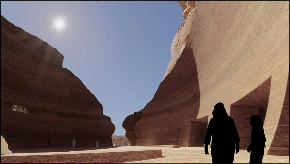 HotelSharaan by Jean Nouvel
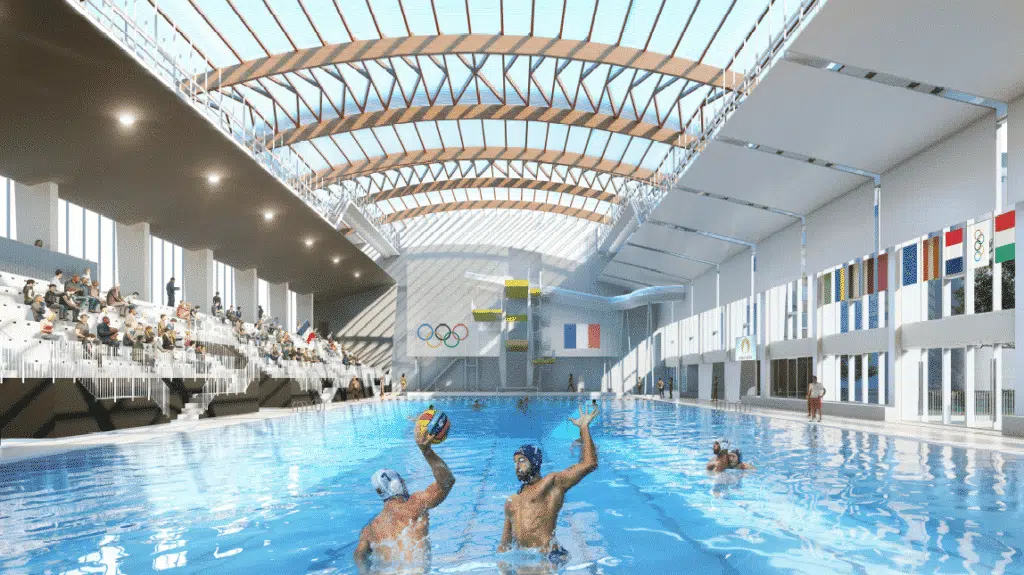 PoolSwimming pool — Montreuil
 IndustryPharmaceutical plant — HVAC
 Natural ventilationPrototype — Natural-ventilation chimney
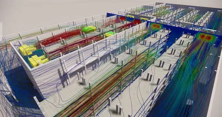 Cold roomCold room — Leipzig
 Sport / ArenaPalais Omnisports de Paris-Bercy
 IndustryPlant — Wind turbine
 Cold roomCold room — Resurfacing
 Atrium · 🔒Glass-roof comfort — Atrium
CFD expertise, delivered projects and technical dossiers: the whole HVAC engineering field in one place.
The simplest thing is to talk it through together. Our engineers reply with an initial technical read.