
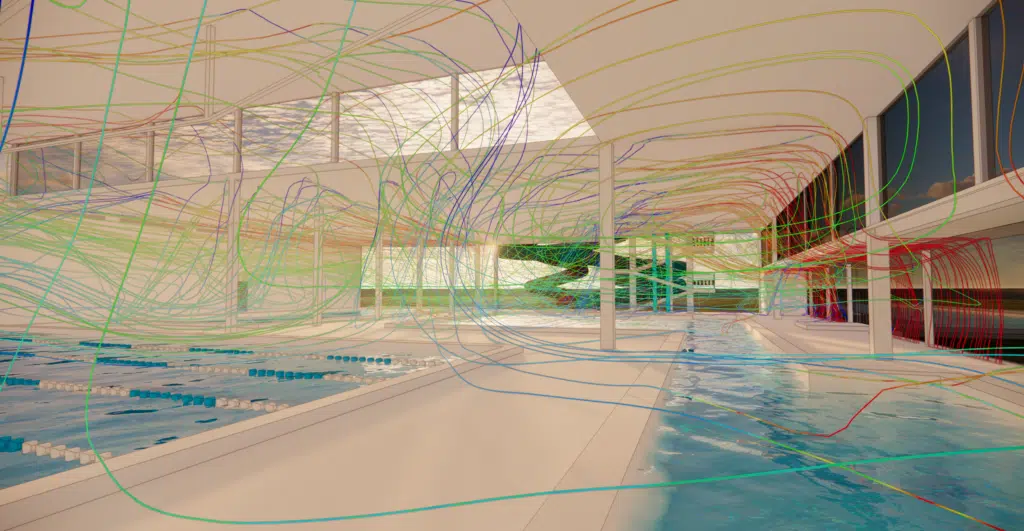
Thermo-airflow CFD simulation of an aquatic center: user comfort, energy performance and control of the condensation risk.
This study focuses on the analysis of the thermal and aerodynamic conditions within an aquatic center, to guarantee user comfort and the energy efficiency of the facility. The aim is to check the air velocities so they do not exceed the discomfort thresholds, to analyse the temperature distribution in the hall, and to confirm the ability of the walls to provide adequate thermal insulation.
The major challenge remains the assessment of the condensation risk on the surfaces, particularly the walls, which could cause significant moisture problems and affect the durability of the structure.
This space is characterised by a warm and humid environment (around 27–28 °C and 60–65 %RH), where water evaporation and condensation phenomena influence heat transfer and the comfort of the occupants.
In short. Thermo-airflow CFD study of a pool hall in a 27–28 °C / 60–65 %RH environment. Floor-level supply sweeps the glazed walls directly (optimal against condensation) and the hall temperature is homogeneous and on target; but some upper walls, less swept, remain condensation-risk zones to be corrected.
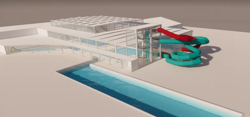
To guarantee accurate simulations, the 3D modelling of the geometry of each element of the enclosure was carried out meticulously, taking into account the position of each beam and each material. This made it possible to visualise and analyse the condensation zones within the pool enclosure.
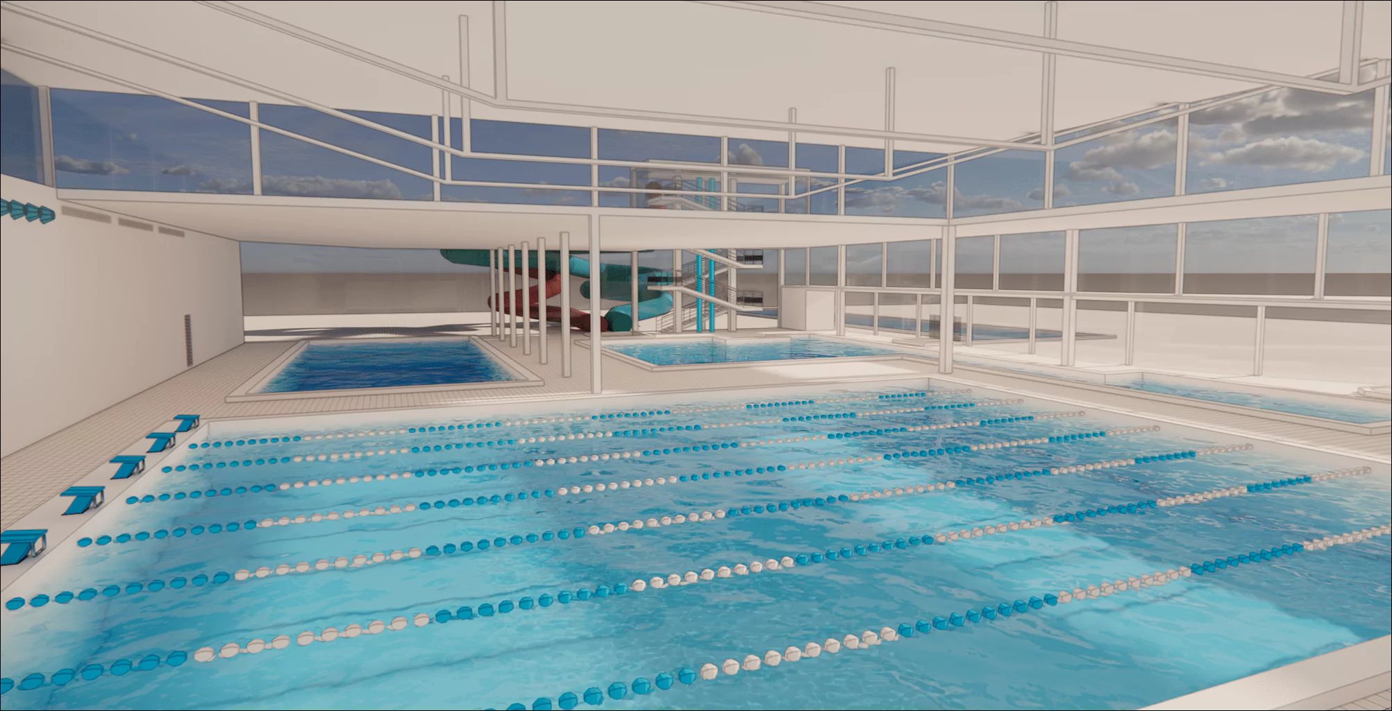
The opaque and glazed walls play a crucial role in the heat exchanges between the inside of the pool and the outside. Opaque materials (concrete, brick, insulation) and glazed surfaces have very different thermal properties (conductivity, insulating capacity), which affects the retention or dissipation of heat.
In our study, all the walls are simulated with accurate heat-exchange coefficients, in order to faithfully model the exchanges, check the effectiveness of the insulation and anticipate the condensation risks.
The temperature at which cooling air reaches water-vapour saturation. Any wall whose surface drops below this point sees vapour condense on it.
The ratio of the water vapour in the air to the maximum it can hold at that temperature. In a pool hall we target 60–65 %RH: beyond that, condensation and discomfort rise.
The supply introduces treated fresh air (often at floor level along the glazing); the extract removes stale, humid air (near pools and stands). Their balance shapes the air sweep of the hall.
Ventilation is essential to maintain a comfortable indoor climate, manage humidity and avoid condensation. The supply distributes fresh air (ceiling diffusers or near glazed surfaces to minimise cold draughts); the extract draws out the stale and humid air (grilles near the floor or the pools, where humidity accumulates). CFD studies optimise the position of the grilles for an efficient and comfortable airflow, without disturbing turbulence.
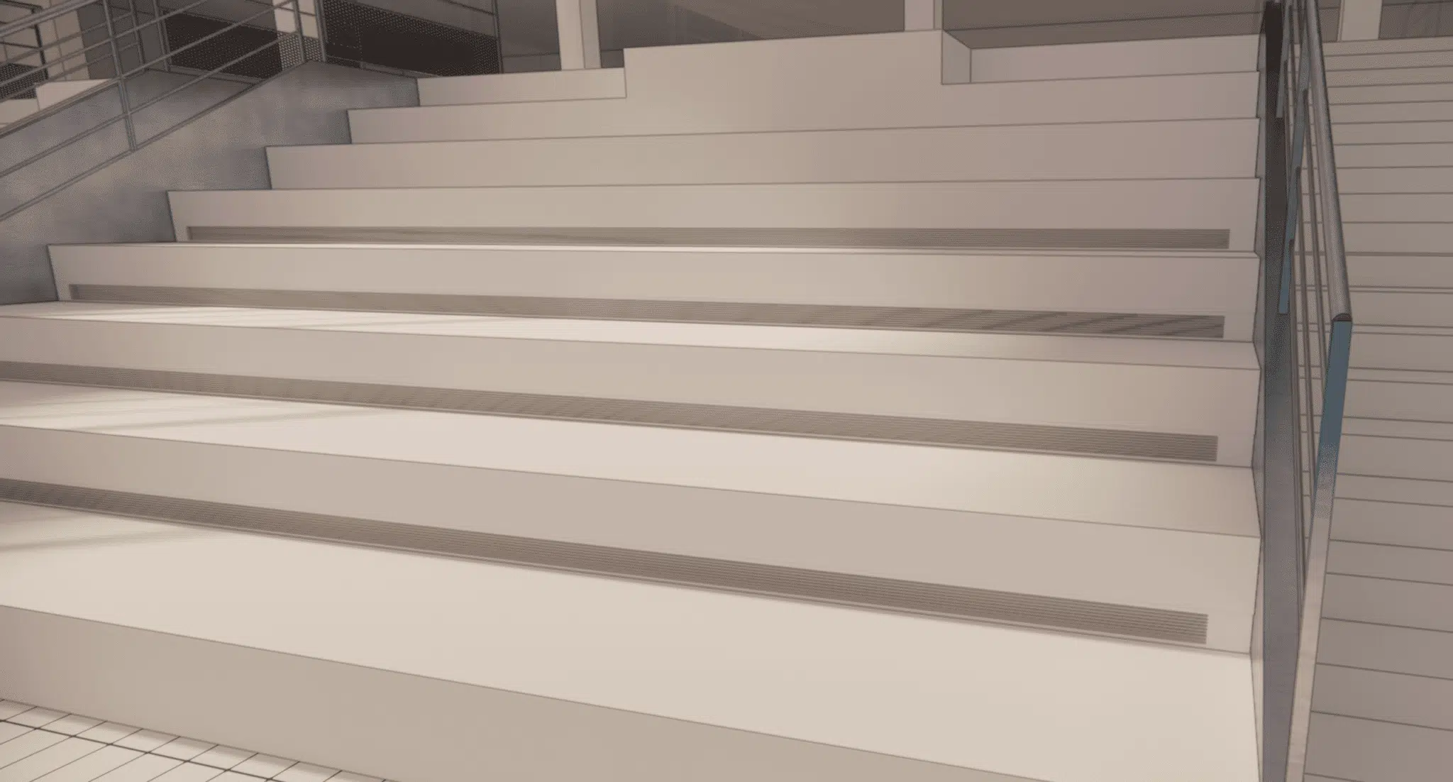
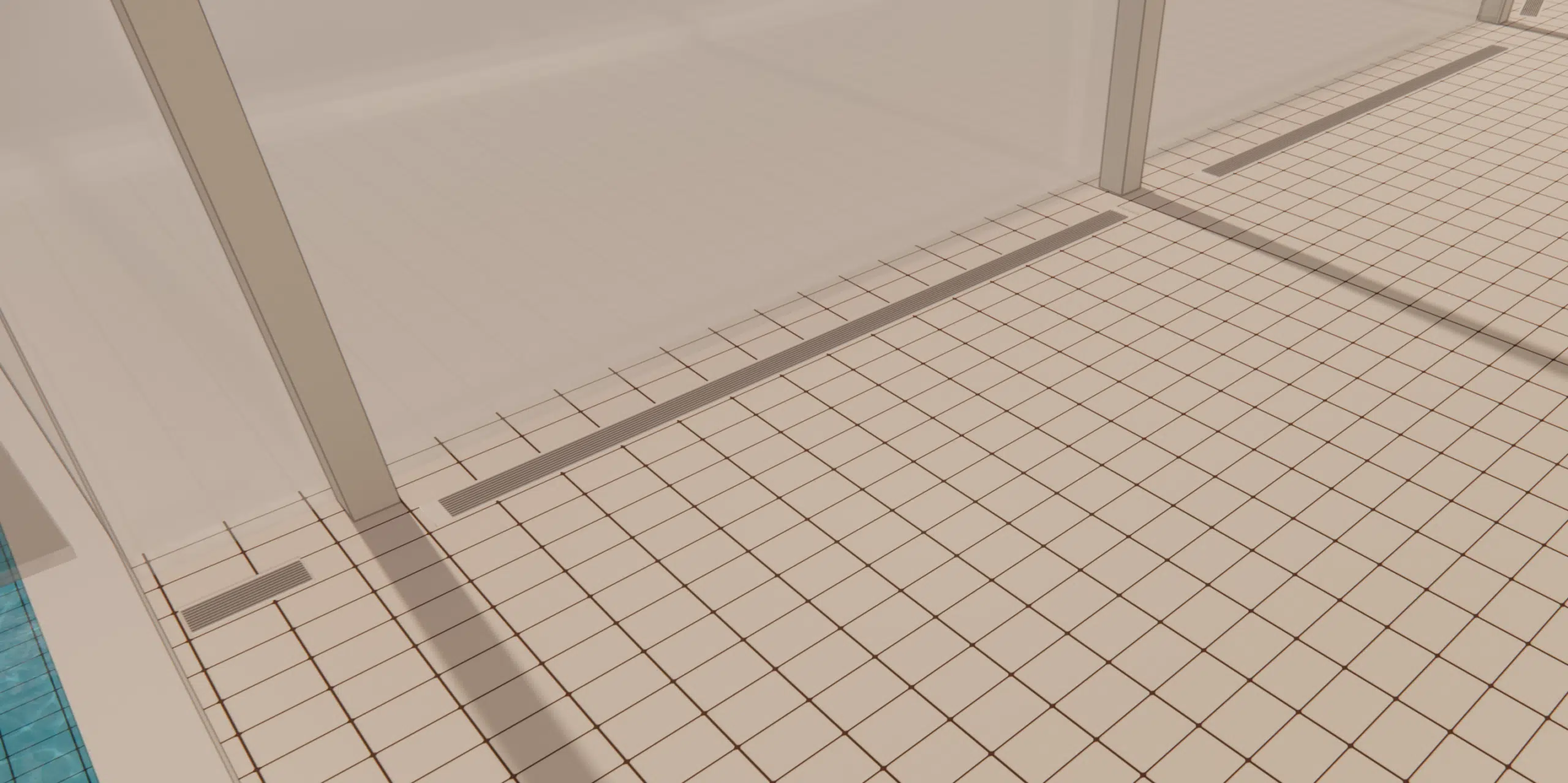
A CFD study for an aquatic center is essential to maximise user comfort and energy efficiency: it models the distribution of temperatures and airflows, identifies the condensation risks in a very humid environment, assesses the effectiveness of the HVAC systems to reduce energy consumption, and facilitates regulatory compliance (air quality, humidity).
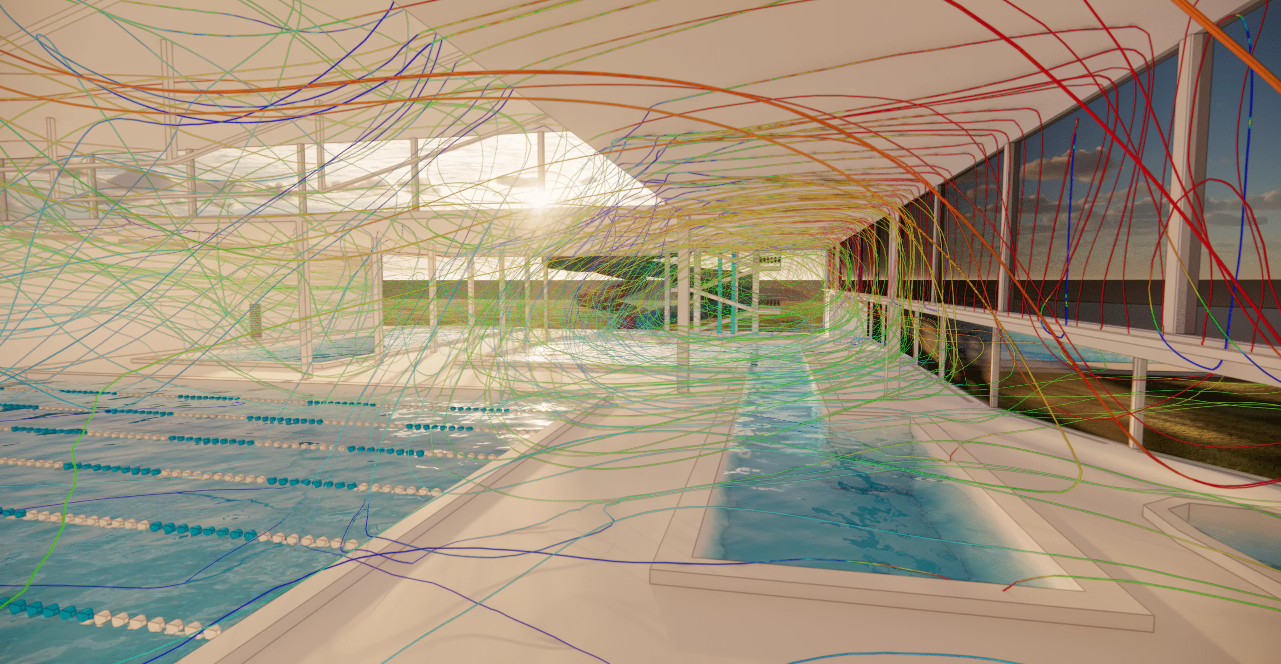
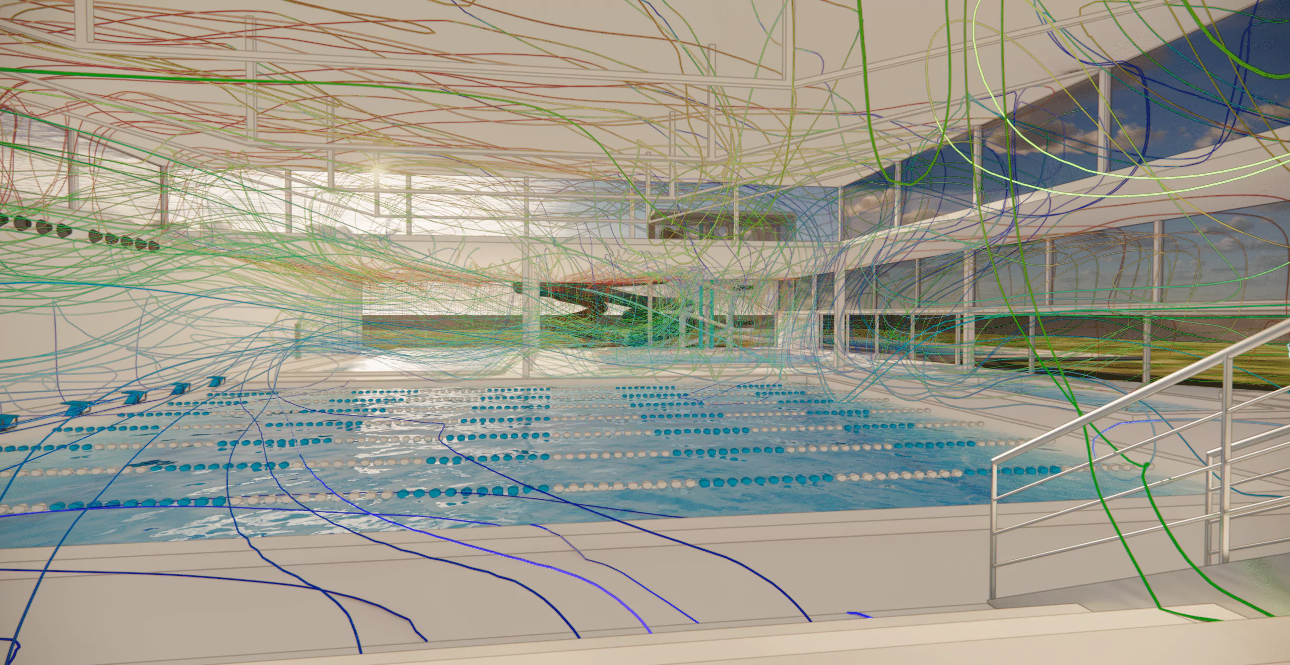
The air velocities around the pool and the stands must remain low to avoid thermal discomfort, and homogeneous to avoid stagnation zones. In this study, some velocities appear a little too high in places (particularly at the air-extract points). The air supplied at floor level sweeps the glazed walls directly (optimal against condensation); the walls higher up, less swept, constitute risk zones.
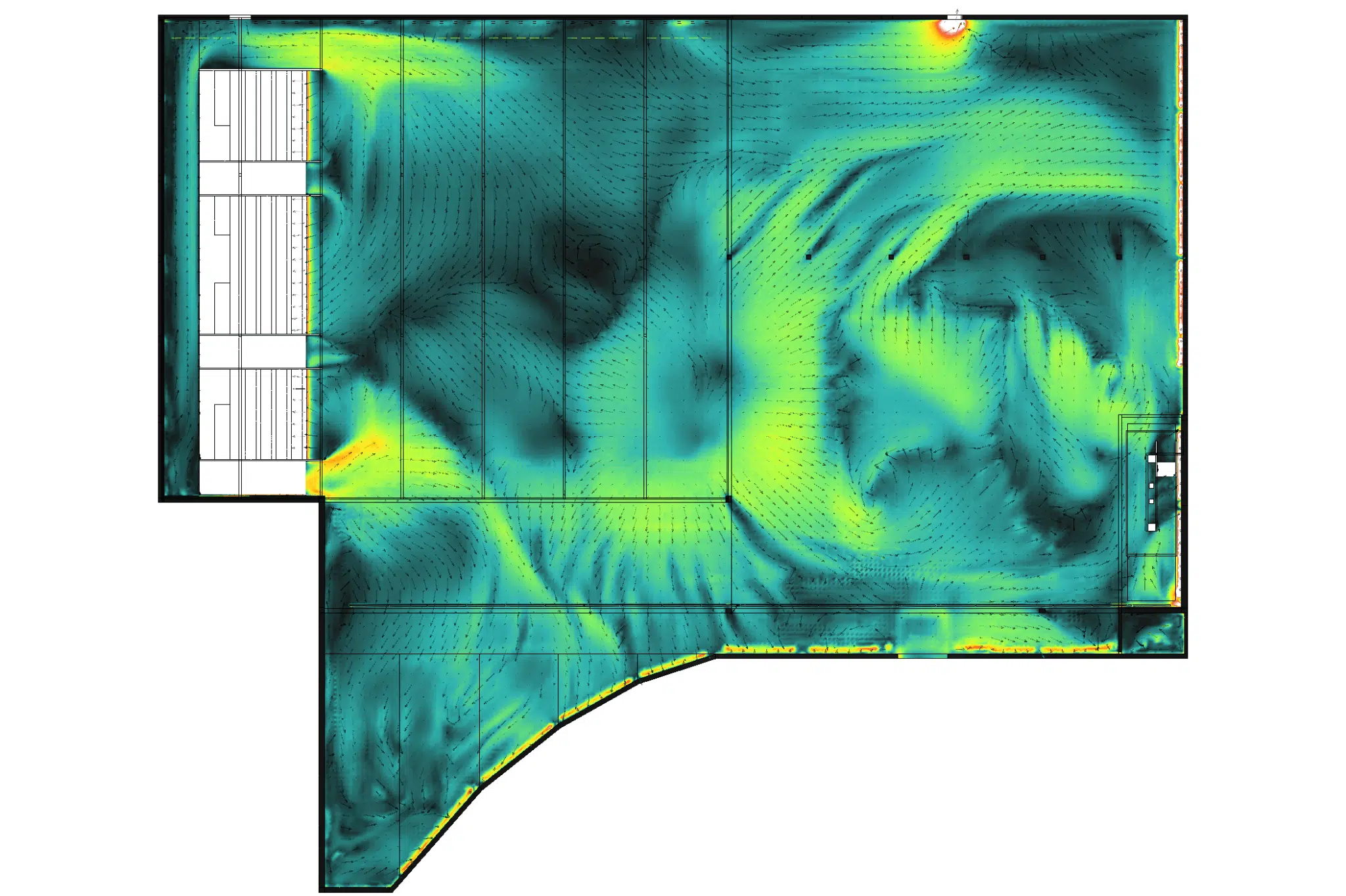
Comfort largely depends on the ambient air temperature (ideally 28–30 °C): too cold, thermal shock when leaving the water; too warm, a feeling of suffocation. In this study, the hall temperature is homogeneous and reaches the target, and the air near the supply and extract points is consistent with the thermal-regulation objectives.
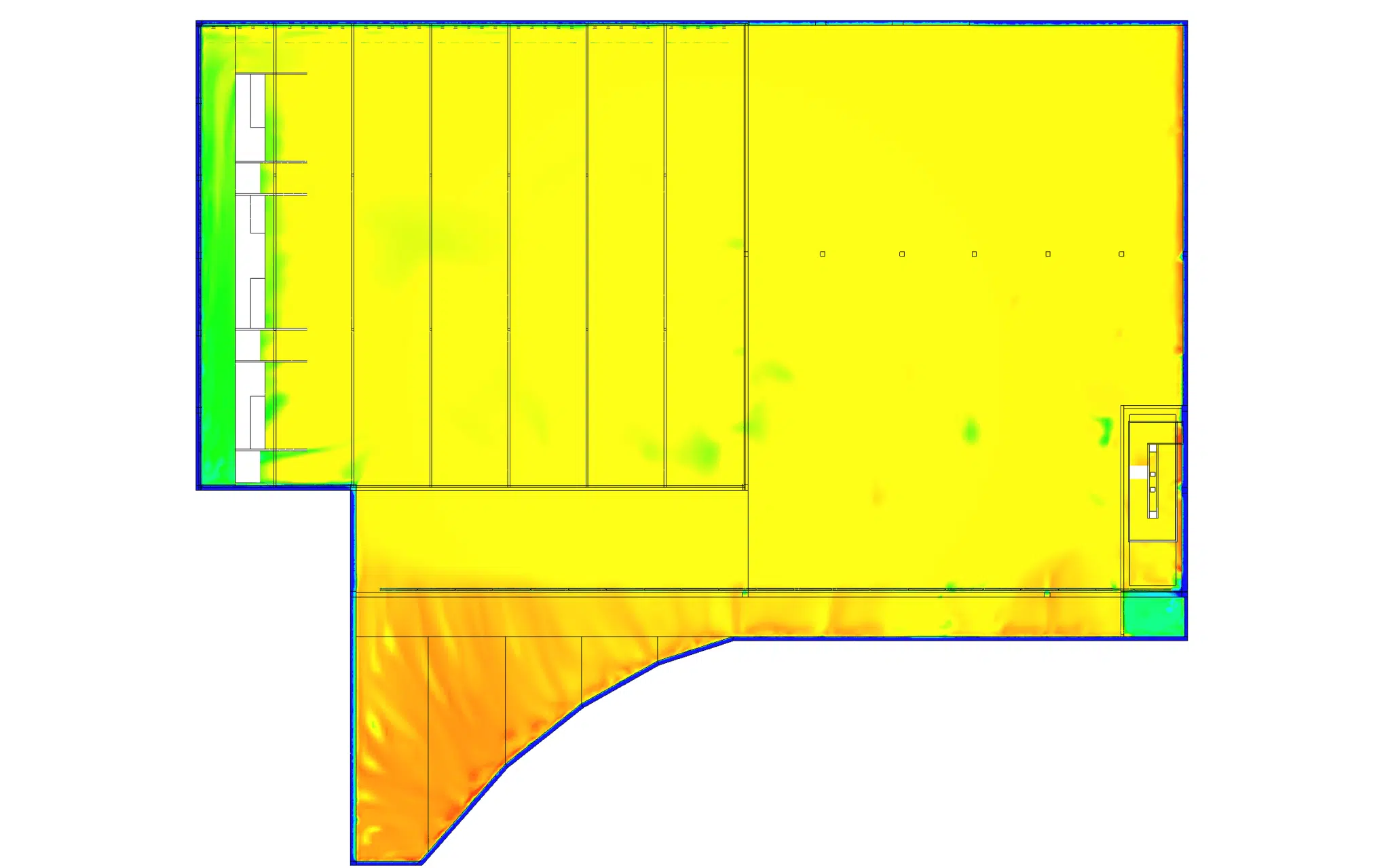
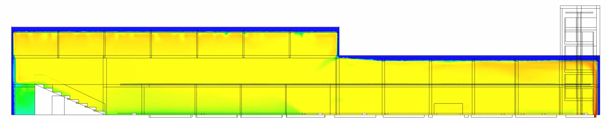
Assessing the condensation risk is crucial: on walls that are too cold, water vapour deposits and triggers a cascade of disorders.
Structural damage — moisture builds up, damages materials and compromises the durability of the building.
Mould & air quality — fungal growth degrades hygiene and the health of users.
Discomfort & safety — slippery surfaces and reduced visibility through fogged glazing.
Energy inefficiency — over-consumption of heating and ventilation to compensate.
Here, the supply and extract provide a homogeneous sweep of almost the entire hall. However, the temperature of some walls is too cold, which poses risks of condensation, mould and unpleasant draughts.
Key takeaway. A globally compliant hall can hide upper walls that are too cold: these are the ones that condense, encourage mould and create draughts. CFD locates them so supply and insulation can be tuned before construction.
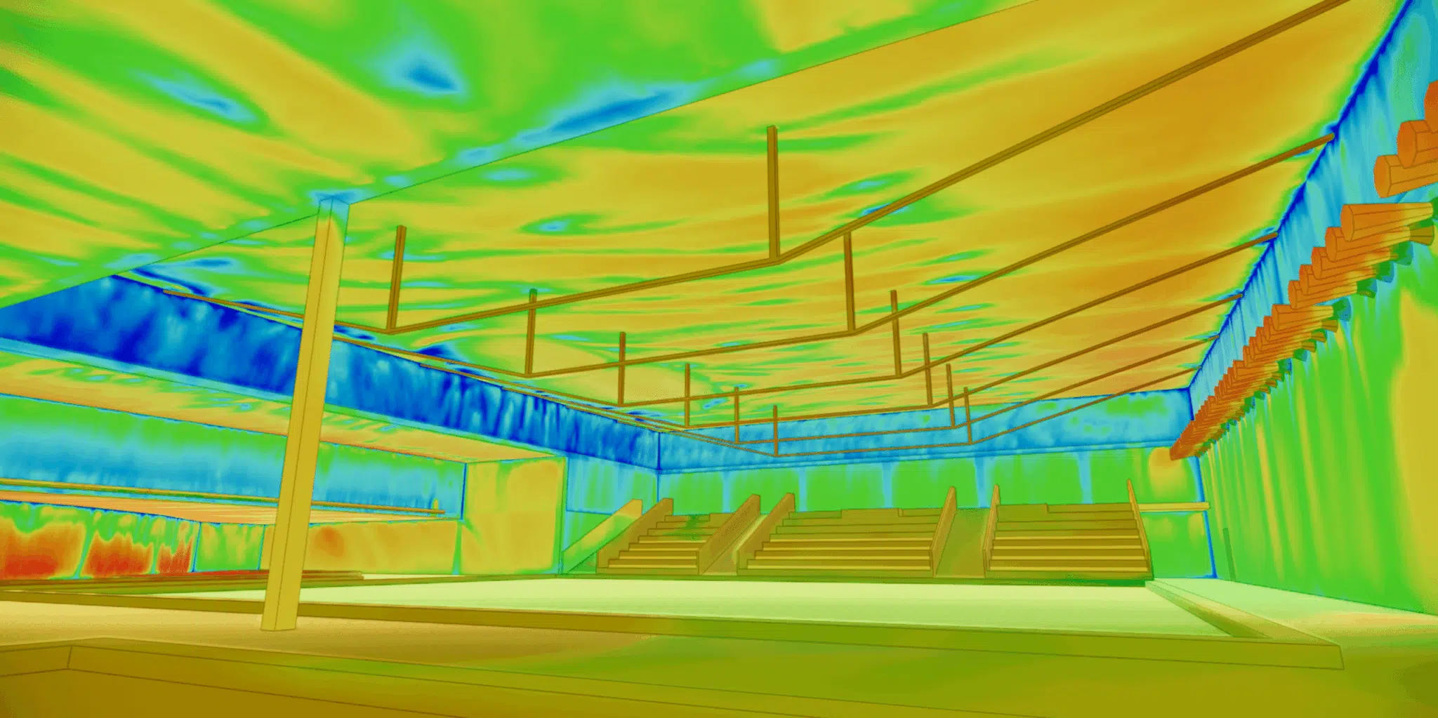
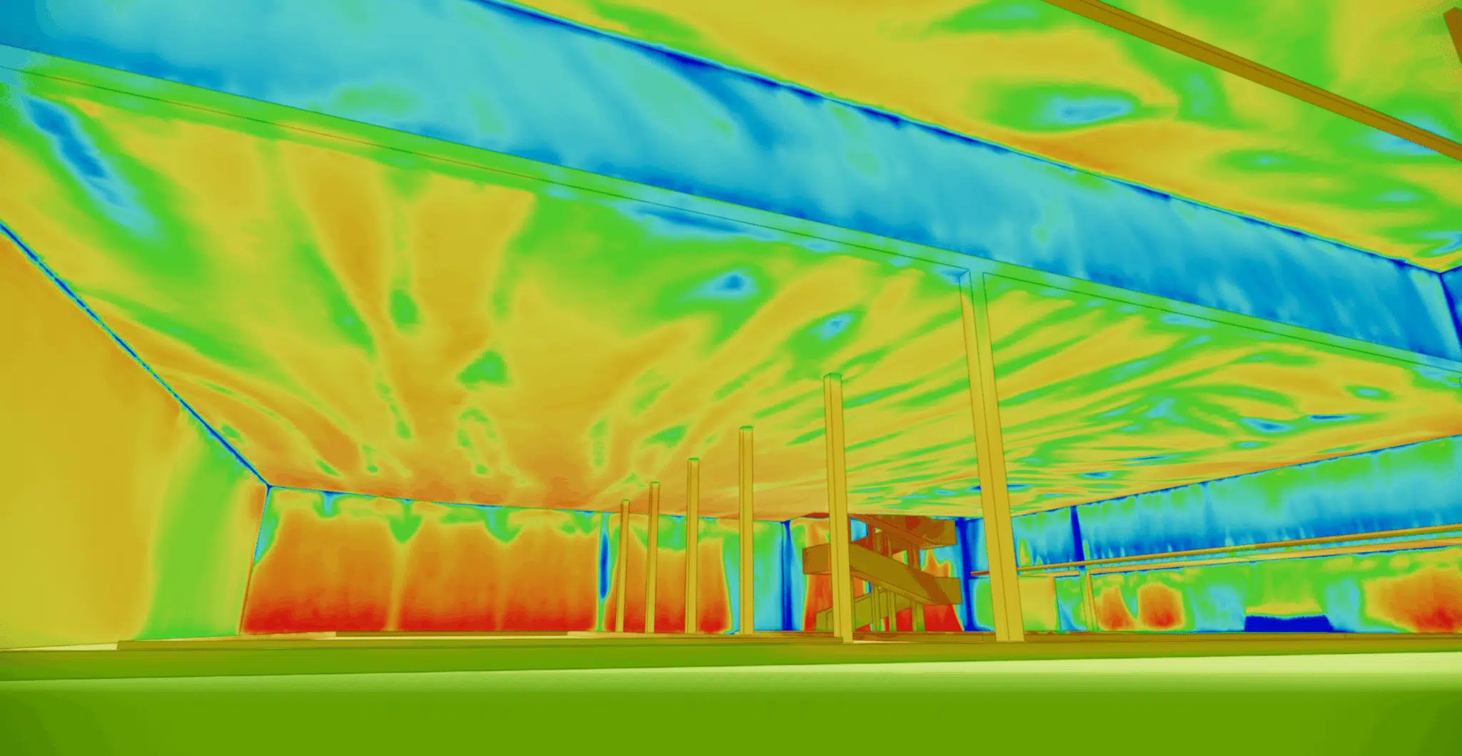
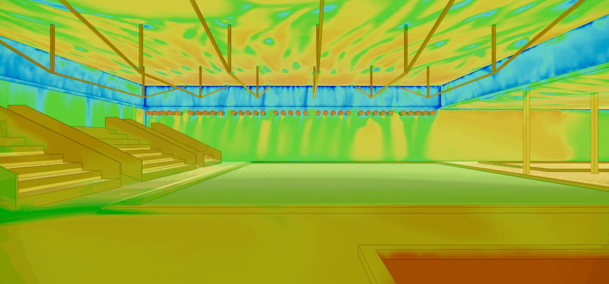
The CFD study is particularly relevant: it models the thermal distribution accurately, identifies the problem zones, simulates different ventilation scenarios and optimises the design of the heating and ventilation systems to achieve an adequate thermal balance — guaranteeing a healthy and comfortable environment for all users.
Know-how: airflow simulation of swimming pools and aquatic centersAnswers to the questions we are most often asked before launching a study.
Every surface must be kept above the dew point and swept by a sufficient airflow. CFD locates the cold, poorly ventilated walls (often the upper ones) so supply and insulation can be tuned. The behaviour of warm air rising and stratifying is governed by the thermal draught effect.
Around the pool and the stands, velocities that are too high create a cold-draught sensation, especially when leaving the water. The aim is a balance: enough air to sweep the glazing, not so much that comfort suffers — a trade-off at the heart of thermo-aeraulic comfort optimisation.
It comes upstream, when no test is possible, and returns the full 3D field (velocities, temperatures, humidity) that a handful of sensors cannot capture. It complements measurement rather than replacing it — see why CFD is an alternative to wind-tunnel testing.
Glazing is the coldest surface and therefore the most exposed to condensation. Simulating it with real heat-exchange coefficients predicts where air must be supplied — an issue common to all large glazed volumes, as shown by our expertise on climatic comfort of glass roofs & atriums.
Yes: the physics of large, busy volumes recurs in gymnasiums, ice rinks and covered arenas, where thermal comfort and air quality are decisive. That is the focus of our expertise on the microclimate of sports facilities.
Explore our expertise, projects and technical papers to go beyond the FAQ.
Thermo-airflow CFD simulation of an aquatic center: detailed 3D modelling of the pool hall, supply and extract principles, distribution of air velocities and temperatures, and analysis of the wall condensation risk for optimal comfort and controlled energy management.
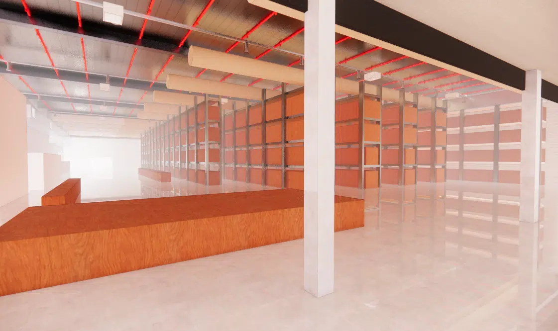 WarehouseHVAC engineering — Medical warehouse
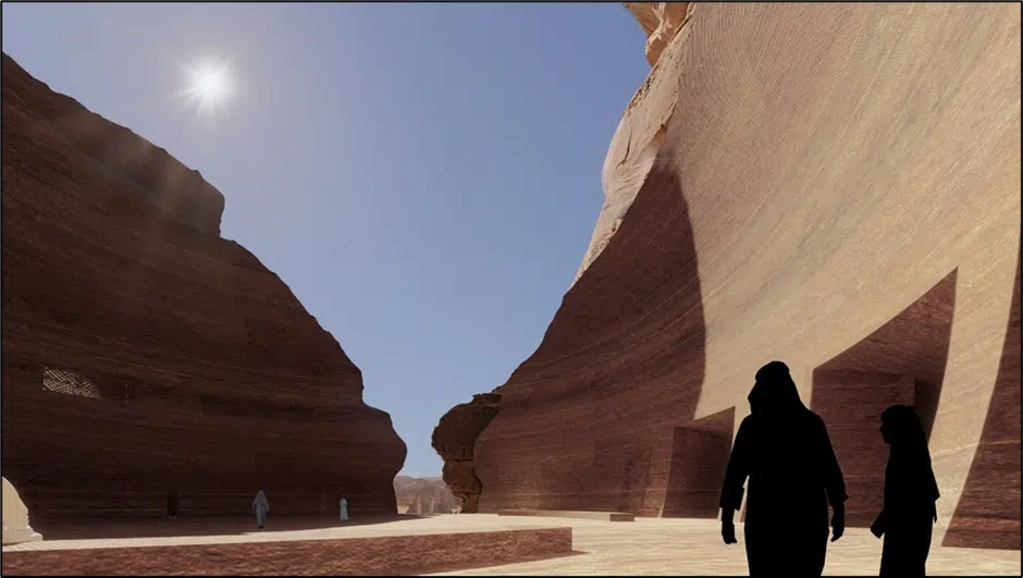 HotelSharaan by Jean Nouvel
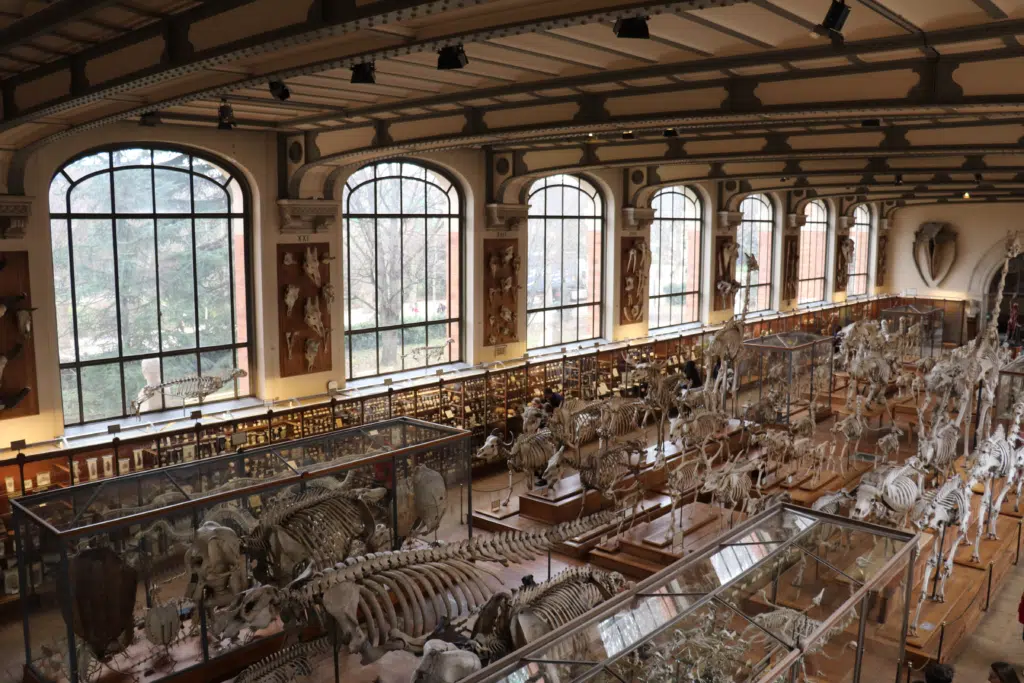 MuseumPalaeontology Gallery — MNHN
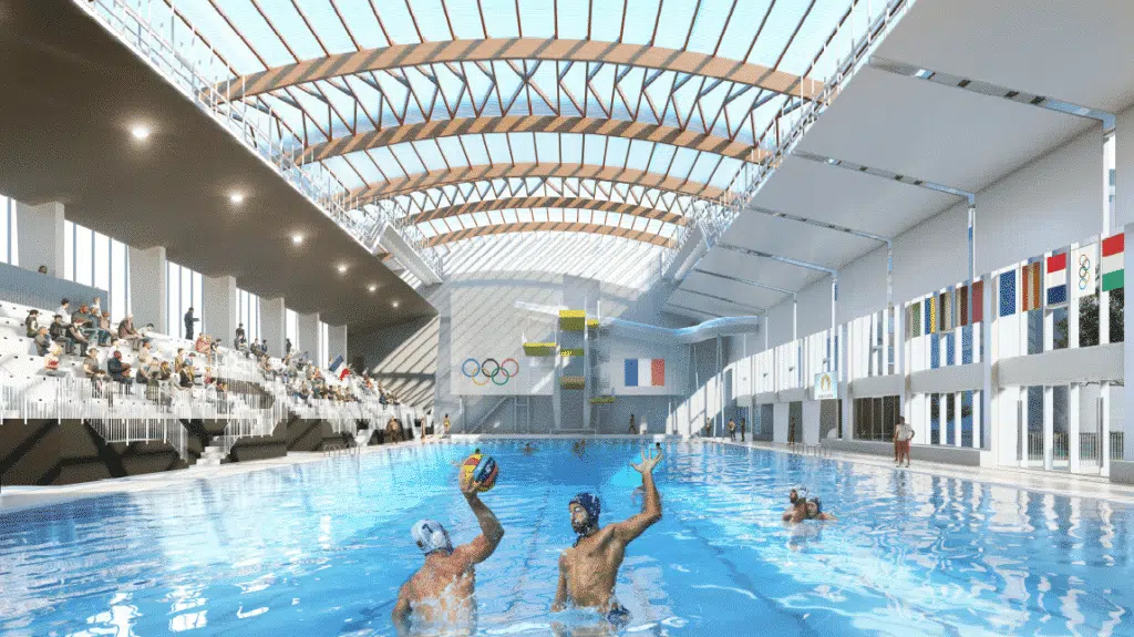 PoolSwimming pool — Montreuil
 IndustryPharmaceutical plant — HVAC
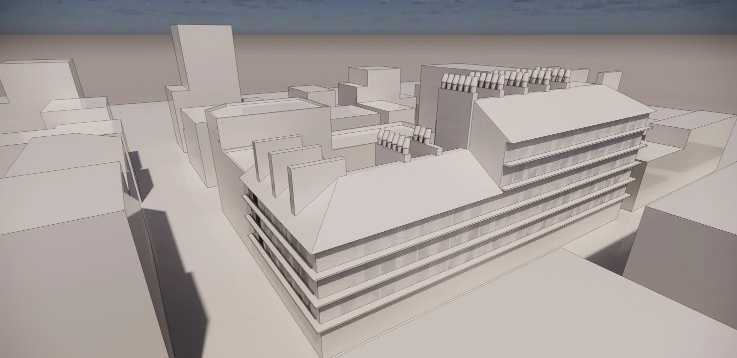 Natural ventilationPrototype — Natural-ventilation chimney
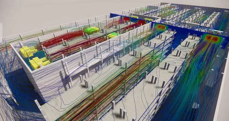 Cold roomCold room — Leipzig
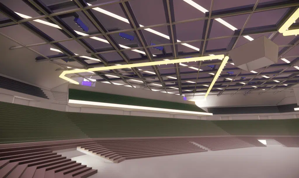 Sport / ArenaPalais Omnisports de Paris-Bercy
 IndustryPlant — Wind turbine
 Cold roomCold room — Resurfacing
 Atrium · 🔒Glass-roof comfort — Atrium
CFD expertise, delivered projects and technical dossiers: the whole HVAC engineering field in one place.
The simplest thing is to talk it through together. Our engineers reply with an initial technical read.