In a few words:
Our EOLIOS engineers, experts in modelling and fluid mechanics, had as an objective the study of the optimization of the comfort of the operators all along a production line by taking into account the surrounding constraints (temperature and speed of ambient air, evacuation of smoke) and in particular at the level of the arches.
The challenge of such a project is the control of the particular thermoaerulic phenomena induced by the different manufacturing steps at very high temperature in the area.
Within this framework our EOLIOS engineers studied by CFD thermo-aerodynamic study the various aeraulic and thermal principles governing the air movement in the plant according to the configuration of the selected systems.
Industrial workshop
Year
2023
Customer
NC
Location
Mexico
Typology
Industry
Continue browsing :
Our other projects :
Latest news:
Sizing the natural ventilation of an industrial workshop
Our EOLIOS engineers encountered numerous constraints due to the characteristics of the site and the construction:
- radiant wall temperatures, which have a major impact on thermal comfort
- thermal draught from manufacturing processes
- wind pressure and internal resistance to vertical airflow
- location and flow resistance characteristics of enclosure openings
- local terrain and immediate wind protection of the building structure
- the presence of mechanical systems that circulate air around production elements, making traditional design complex
As the building is not air-conditioned, the only source of cooling is the supply of fresh air by natural draught to the static roof ventilators, or by forced ventilation. Improving thermal comfort therefore requires precise sizing of natural ventilation openings.
Our engineers have responded to various problems such as
- Evacuate smoke and gases produced by the arches (in particular by internal burners)
- Sizing of natural or mechanical ventilation in relation to the new extension to the palletizer building.
- Propose solutions to optimize thermal comfort and air quality.
- Limit dust and mosquito infiltration.
Air pollution problems specific to the workshop
The production workshop has specific constraints linked to natural ventilation processes.
The use of ventilation is diverse:
- Combating overheating to maintain acceptable working conditions and ensure smooth operation without human or material risk
- Air supply for the various fans and blower systems on the machines
In this context, 3 sources of outdoor air pollution lead to difficulties in ventilation management:
- Area with flies, mosquitoes, and other insects with a diameter close to the mm.
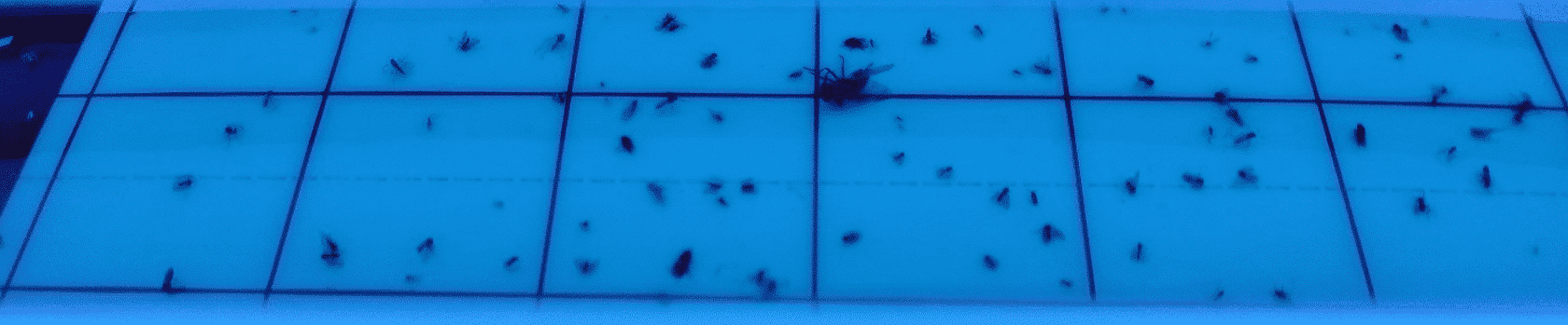
- Residues of sugar cane combustion (ashes) of the order of mm, which originate from the exploitation of fields in the region. These are the residues most frequently identified in sand screen systems equipped with double screens.
-
A fine dust from the surrounding land. The dry climate combined with the very fine sediment of the land leads to the natural blowing of dust in the presence of wind. This phenomenon is accentuated by the presence of activity on these dry grounds (passage of trucks, trampling…) and quarries in the area. The fine dust from the site, once blown away, does not fall back and can be transported over several hundred meters.
Smoke audit
The objective is to carry out an assessment of the systems in place, to measure the interior temperature conditions and to characterize the main thermo aeraulic conditions of the space in order to establish an assessment of the installations in place. In industry, we can carry out smoke audits in order to calibrate the numerical simulations with respect to real phenomena.
Videos of the smoke audit
Among other things, the audit consists of taking air temperature and air speed measurements , analyzing the movement of smoke bombs, producing a video support and an audit report allowing feedback of experience for all the actors. Additional recommendations (use of louvers, cellar access doors, etc.) will be made based on the various observations on site.
This page broadly details the conduct of the audit in order to explain our mission protocol.
Air movement with other rooms in contact with the production workshop
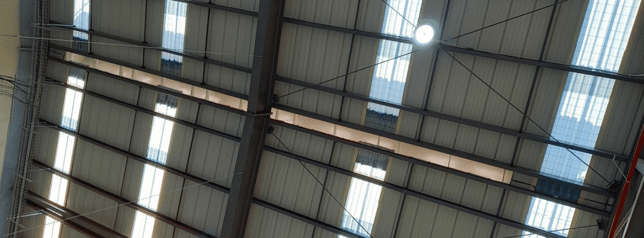
The production workshop is an area where the climate is managed by natural ventilation. As such, it is not equipped with a mechanical system, and air circulation is supposed to be ensured by a natural transfer between the air inlets on the lower level and a natural extractor on the roof.
The site teams alerted our experts to the presence of dust and residue from the static aerator on the floor in the clean process area.
Our analysis highlighted the fact that a significant amount of air is transferred to the decor area and then to the packaging area. In fact, these zones are equipped with mechanical roof ventilators, which contribute to the negative pressure compared with the naturally ventilated zone.
Natural industrial ventilation
Natural ventilation (for small temperature differences) is provided by thermo-aerodynamic motors with very low pressure delta. The presence of sand barriers, which increase the pressure drop across air inlets, leaves the static aerator as the preferred transfer zone (simple external orifice).
In this context, air intake via the roof is favoured as soon as a Fenwick passes by in the direction of the annex room. When the Fenwick doors are opened, air is drawn in via the roof vent: air speed in the doorway >1.7 m/s (i.e. a transfer of around 100,000 m3/h).
In this context (building connected in natural ventilation to buildings under mechanical extractions by adding important losses of load to the natural entries). Our engineers have concluded that it will not be possible to operate this static aerator satisfactorily in natural extraction.
Increasing the number of air inlets would limit this phenomenon slightly, but the pressure drop across the sand seems too great to prevent the building from being mechanically depressurized via air transfer.
Conclusion of the site audit
The production workshop suffers from problems linked to its exposure to the sun and the presence of systems releasing very large quantities of calories. The air velocities are slightly higher than for the adjacent building due to the ratio of openings to the size of the building.
The systems also contribute to overheating the space by releasing a plume of overheated air at the inlet and outlet, which dissipates into the atmosphere. They are the main driver of air movement in the area.
Optimization of thermal ventilation comfort
CFD modeling of industrial processes
The thermal characteristics of the walls and the process are taken into account. The values integrated in the CFD calculation are the simulated values of the project.
In a digital model, the elements are as they are described, and only as they are described. When it comes to building envelopes, this often leads to surreal perfection: materials are perfectly homogeneous and perfectly implemented. The only thermal bridges are those described, and it is at best very complicated, if not impossible, to anticipate all thermal bridges (structural thermal bridges and those related to the attachment system are generally taken into account; thermal bridges due to holes or network passages are generally not).
The main challenge of this tab will therefore be to distinguish between the target value, resulting from the performance of the materials, and the simulated value, taking into account the inevitable imperfections of implementation.
CFD modeling of natural ventilation systems
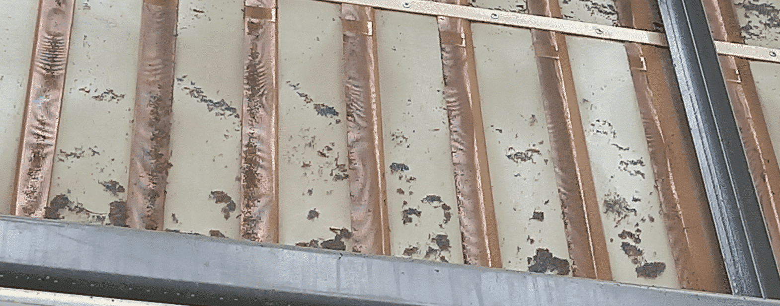
Sand guards equip most of the air transfer vents from the outside.
The sand screens are equipped with mosquito nets on their inner sides.
In the CFD study the sand pare modeled in such a way as to obtain an equivalent air flow without constraining the numerical model.
3D CFD model
The aim of this chapter extract is to outline the 3D model produced for the basic CFD study. The specific features of CFD models, linked to the robustness of their solver and the quality of the 3D model, mean that the geometry model has been entirely remodeled. Simplifications, related to curves, edges, points and small elements have been made.
The external CAD model produced shows the geometry of the site without its surroundings. It was made from the section plans and the revit model of the project.
The model is designed to take into account the air and heat transfers in the hall.
Our EOLIOS engineers have paid particular attention to industrial system modeling to ensure maximum accuracy. Indeed, the furnaces being one of the main sources of heat release, they have the greatest impact on the surrounding thermo-aerodynamic phenomena.
The consideration of air masks is important in order to describe the different air movements in the area.
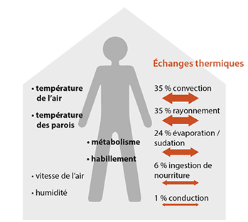
How to qualify thermal comfort in hot spaces?
Thermal comfort is an individual’s satisfaction with the thermal conditions of his or her environment. We speak of thermal comfort when the person wants to be neither hotter nor colder.
It is subjective and therefore depends on individual perceptions. It is influenced by physical activity, clothing and the levels and fluctuations of the characteristics of the thermal environment (air temperature, radiation, contacts, humidity and air speed).
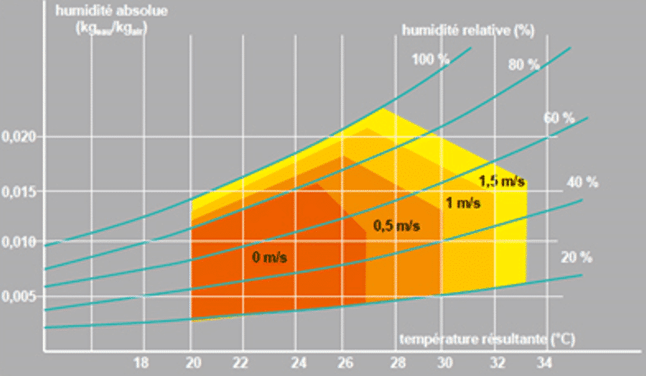
In orange are represented the thermal comfort zones adapted according to the air speeds
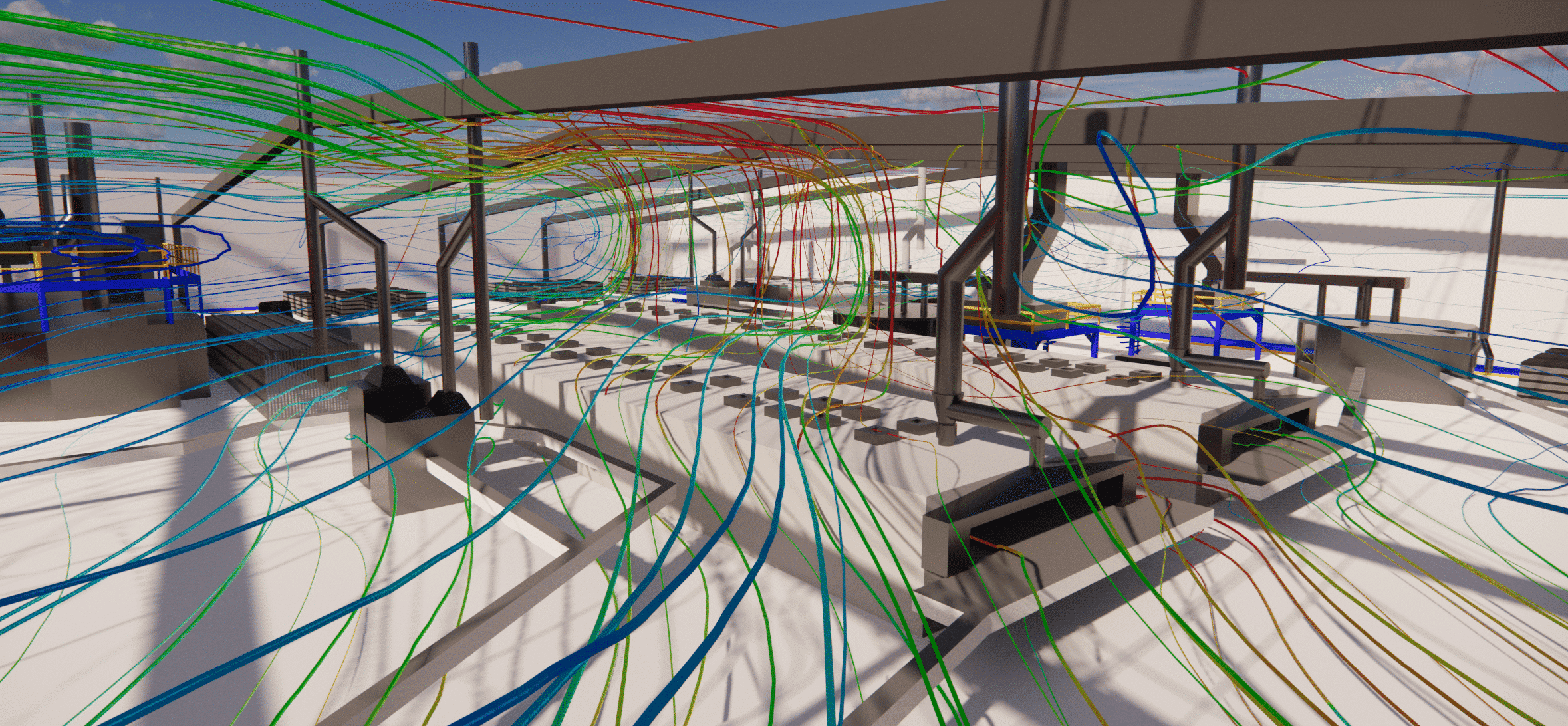
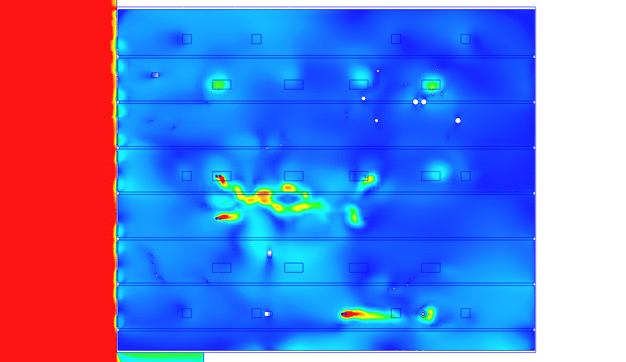
Study of the air velocity distribution
The first figure below shows the effects of volume mixing.
The room’s general aeraulic movements can be described in two stages, induced by the air supply zones constituted by the sand barriers and then by the return zones.
In simple terms, pressure differences are the driving forces behind air currents. In other words, air flows from a high-pressure space to a low-pressure space when these forces are greater than the friction losses.
In HVAC, air circulation is induced by two driving forces:
- Thermal draft occurs when a difference in temperature causes a difference in density between two air masses. This effect is accentuated by a greater height in the volume. “Hot air tends to rise”.
- The distribution of pressures and depressions induced by HVAC systems in the volume.
Here, the return air systems have very little influence on the air velocities inside the building, the air movements are governed by the temperature rise of the oven zones.
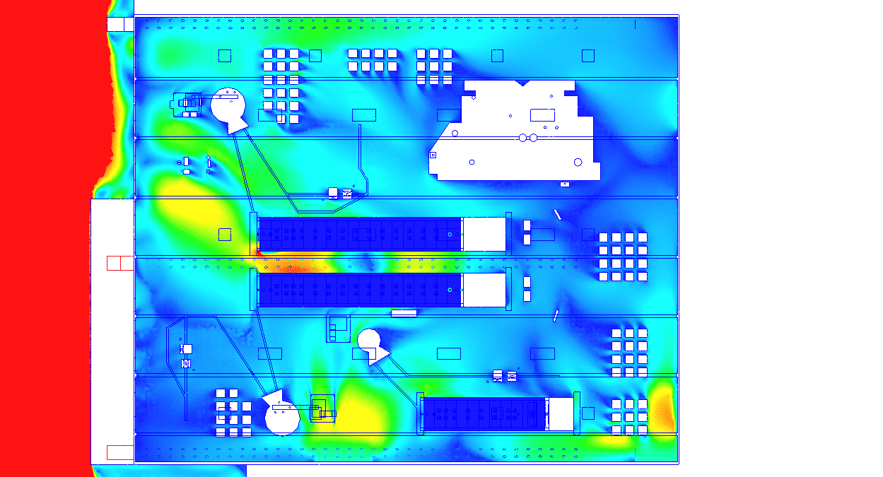
Study of the air velocity distribution
Air velocities are not consistent with comfort objectives for this type of activity in summer. The displacement air velocities are below the target values for thermal comfort in warm environments.
The highest air speeds are found in the continuity of the sandy parts. In fact, these areas are the main air inlets in the hall.
On the other hand, the simulation highlights the presence of a low-velocity zone between the arches, which can lead to a rise in temperature.
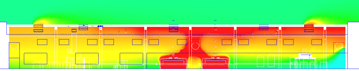
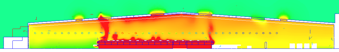
Study of the air temperature distribution
In the absence of movement, or when movement is slow and regular, the air forms layers of homogeneous temperatures that overlap, with the warmest air in contact with the ceiling.
These sections highlight the stratification phenomenon explained earlier.
The air temperature in the building is globally overheated, even in the lower part where the temperature is clearly higher than 35°C
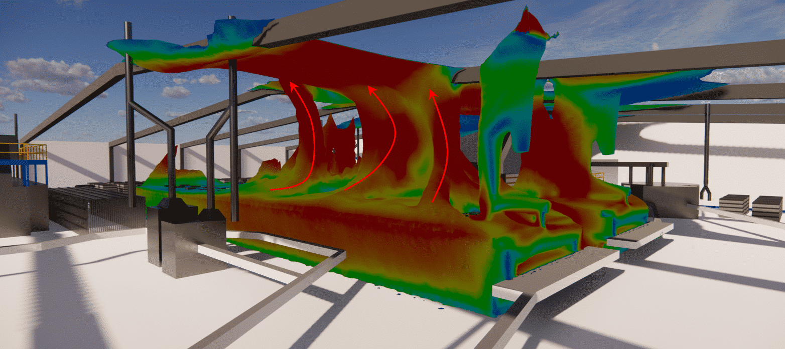
Study of superheated thermal plumes
Iso-surface views of thermal plumes can be used to identify the various sources of heat and their impact on the model.
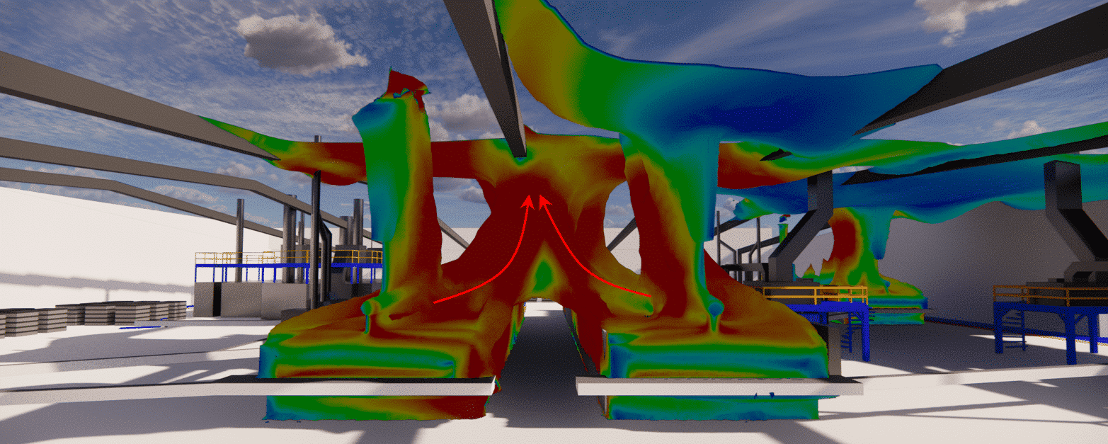
The combination of low air circulation and high furnace temperatures results in high temperature zones. The simulation shows that the air between the furnaces rises in temperature and tends to flow under the ceiling. However, once under a false ceiling, warm air has difficulty being evacuated to the outside.
Moreover, the results of the study show that the hoods at the entrance of the ovens do not allow the suction of all the air loaded with calories. This phenomenon is mainly due to undersizing of the suction flow.
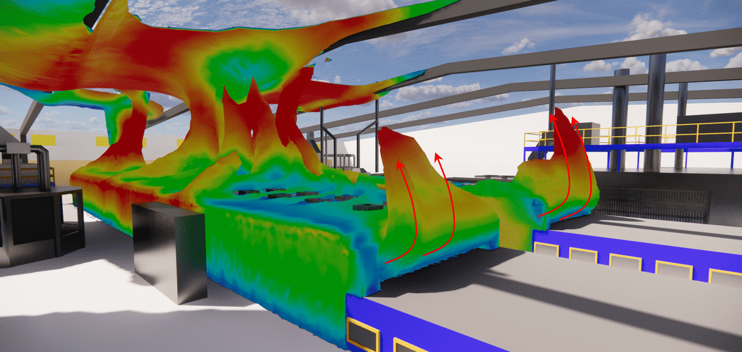
The air coming out of the oven, not being sucked in by a hood, tends to go towards the ceiling. This phenomenon contributes to the rise in temperature of the room.
Another phenomenon not taken into account, but which can have an impact on the aeraulics of the room, is the thermal inertia of the products, which can emit heat into the zone as they leave the furnace.
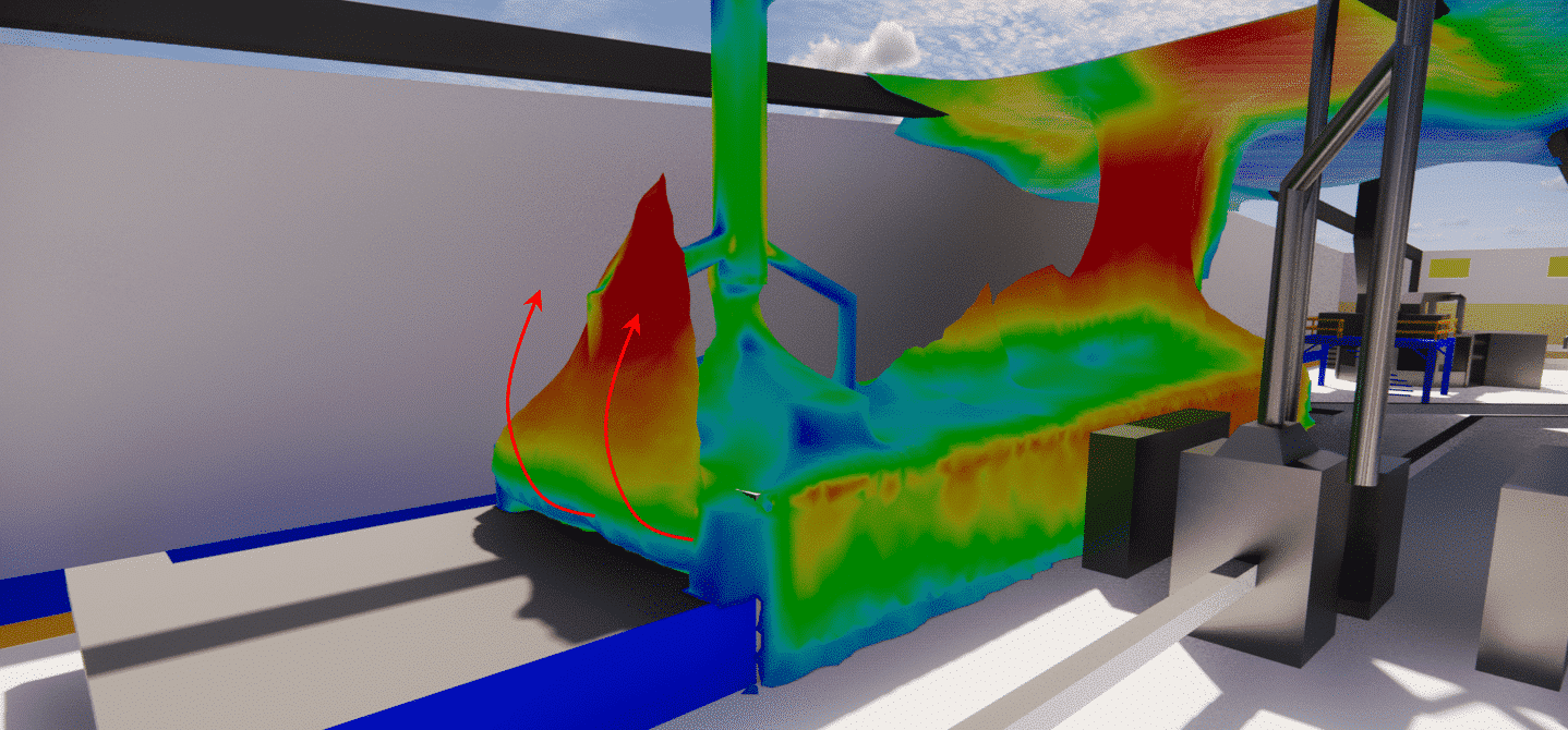
The rear chimney of the oven, which operates with natural ventilation, does not appear to be sufficiently efficient to recover all the heat. Indeed, as highlighted above, the air leaving the oven, loaded with calories, tends to go towards the ceiling, thus contributing to the rise in temperature.
However, we note an operation in extraction (no internal reflux which could have been caused by the depression of the room).
CFD simulation for industry
Numerical simulation opens up new perspectives for manufacturers. This makes it possible to foresee a multitude of scenarios, and therefore to control all the unforeseen consequences of poor design. In the case of production plants, multiphysics modeling enables us to take into account all the phenomena that cause heat and air flows along the production line, from overheating to employee comfort.
Thanks to its calculation servers, EOLIOS models can be simulated in their entirety with a high degree of accuracy in a very short space of time. Moreover, the experience of EOLIOS in general aeraulics allows our team to propose innovative and relevant solutions in the case of overheating problems. Nevertheless, implementing CFD simulations in your design process means calling on experts in fluid mechanics, thermal and numerical simulations to ensure that no problems occur in the future.
Our EOLIOS engineers have extensive experience in auditing, bringing their expertise directly to bear to optimize the resolution of various problems. Their state-of-the-art equipment enables direct and distinct measurements, guaranteeing an assessment of the site, equipment, materials and, if necessary, a thermal expertise including systems, heat loss and climate control through systems.