Study of load losses in data center generator rooms
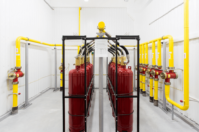
The importance of generators in data centers
How to characterize head losses in a room
Theenergy of a volume of air can be expressed as a sum of pressures, constituting the total pressure of the volume of air:
- The pressure due to the weight of the air column: ρgh,
- Dynamic pressure linked to air speed: ρv²/2,
- Static pressure linked to internal air pressure: P.
A component’s pressure drop is the difference between the total pressures (sum of static pressure, dynamic pressure and pressure due to weight) at its inlet and outlet. Pressure losses in a room are due to the resistances encountered by the fluid (air) as it flows through the various elements of the distribution system (such as ducts, elbows, valves, grilles, etc.).
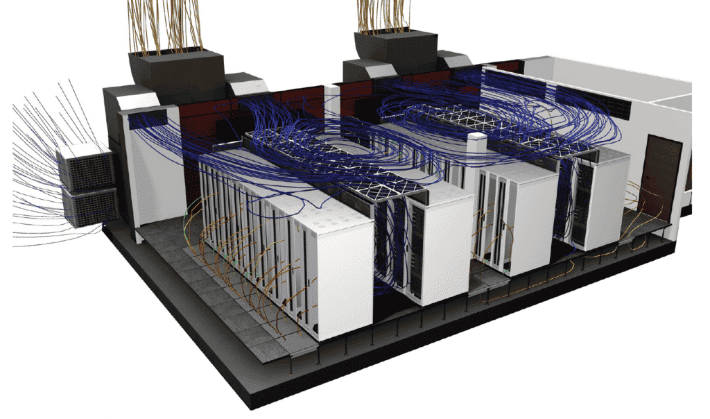
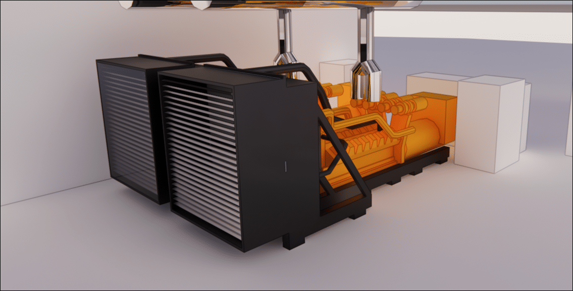
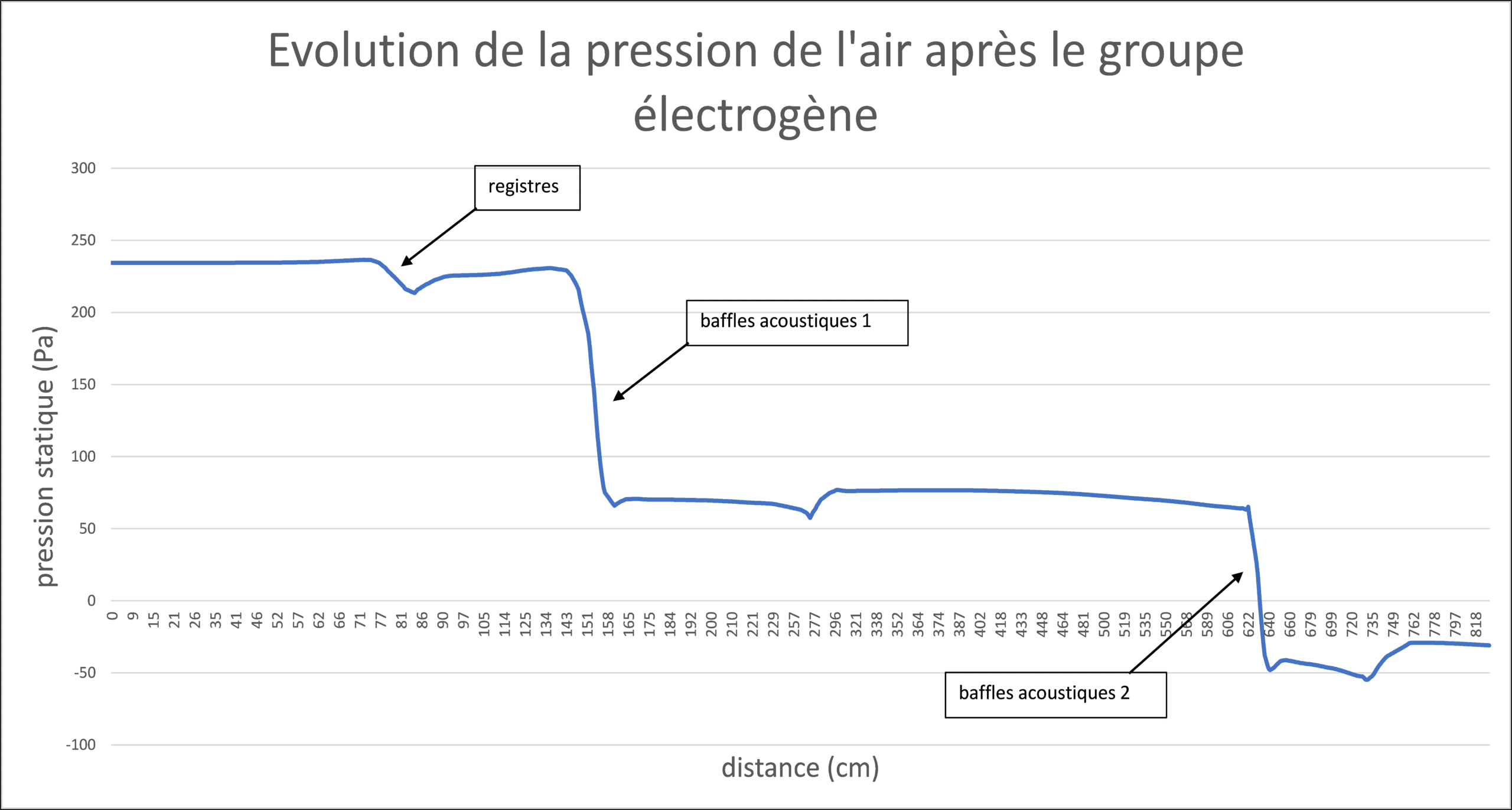
These resistors reduce the pressure of the fluid along its path. In the case of generator sets, acoustic baffles are installed upstream and downstream of the GE to limit noise pollution, which also generates significant additional pressure drops.
Understanding and managing these pressure losses is essential to ensure the efficiency and smooth operation of ventilation, air-conditioning, heating and plumbing systems. Minimizing pressure losses in fluid distribution systems is essential for maximizing energy efficiency, reducing costs and ensuring optimum system performance. This is a key aspect of the design and management of data center generator rooms.
Why carry out a CFD head loss study?
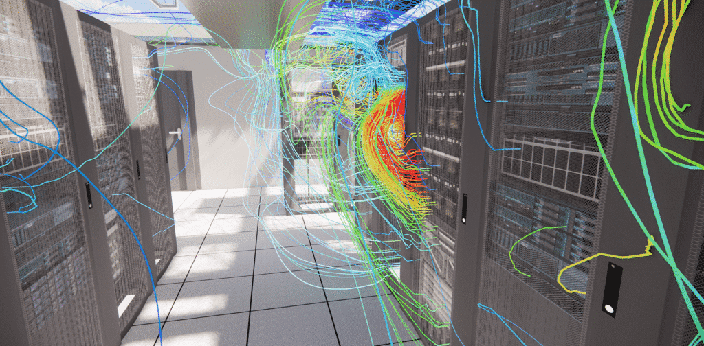
CFD head loss studies are of vital importance in many engineering fields, including data centers. By enabling detailed numerical modeling of fluid flows within a system, this approach provides crucial information on areas of head loss, turbulence and stagnation. Understanding these phenomena enables us toidentify weak points in the system,optimize the design to minimize energy losses,improve systemefficiency andensure optimum performance under various operating conditions.
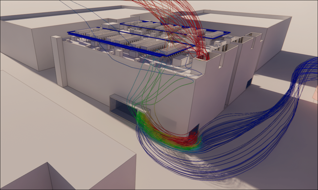
In addition, a CFD study enables the effects of potential modifications to be predicted and simulated before they are physically implemented, providing a cost-effective method of evaluating different improvement and problem-solving strategies. In the case of generator sets, for example, this type of study will help toensure that they operate smoothly in all circumstances. Reducing pressure drops also enables higher discharge velocities to be achieved at roof level, thus reducing the risk of looping phenomena with air coolers.
Where do load losses come from?
Most of the pressure losses generated in data center generator extraction lines are singular pressure losses. Singular pressure losses are caused by sudden changes in pipe geometry, such as bends, constrictions or sudden widening. These pressure losses are due to several factors:
- Formation of vortices and turbulence zones: Sudden changes in geometry cause disturbances in fluid flow, resulting in the formation of vortices and turbulence zones. These vortex structures lead to energy losses, resulting in additional head losses.
- Flow acceleration and deceleration: When a fluid passes from a wider to a narrower section of pipe (narrowing) or vice versa (widening), it undergoes a change in velocity. The sudden acceleration or deceleration of the flow causes pressure losses, as kinetic energy is converted into pressure energy.
- Wall friction: Irregularities in the surface of pipe inner walls, particularly where geometry changes, can lead to increased resistance to fluid flow. This resistance translates into additional head losses.
It’s important to note that these singular head losses can be reduced by adopting an appropriate pipe design, using smooth connections and ensuring a gradual transition between different pipe sections. Good hydraulic design can minimize these singular head losses and optimize flow efficiency in the system.
Numerical simulation of pressure losses
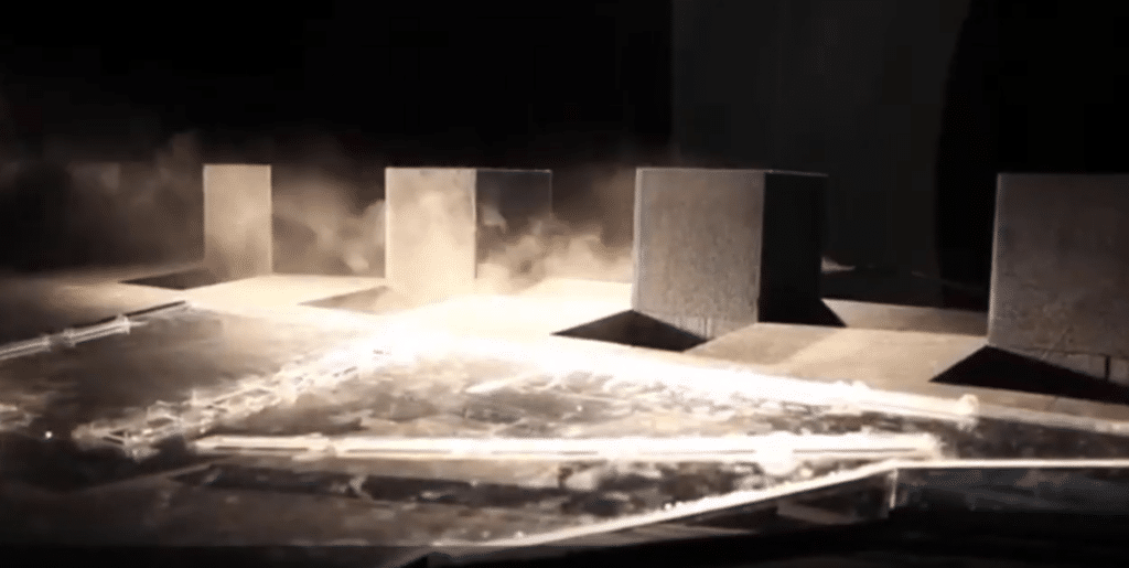
Modeling process for CFD study
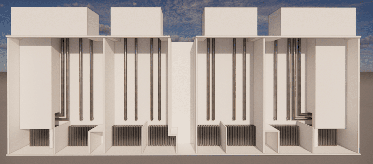
To create a 3D model of a plant room for CFD study, the approach followed was based on the plans and 3D model of the process. The entire process, including generators, sound traps, chimneys, room elements, ducts and plenums, was accurately represented. Using 3D modeling software, geometric models of the parts were created, integrating process equipment and obstacles, while respecting their actual location.
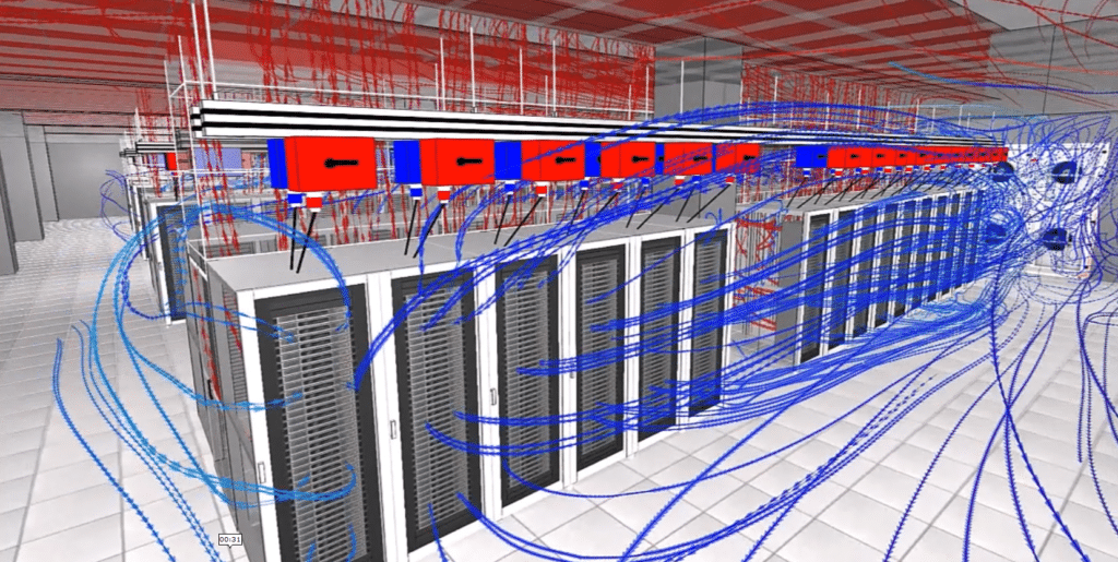
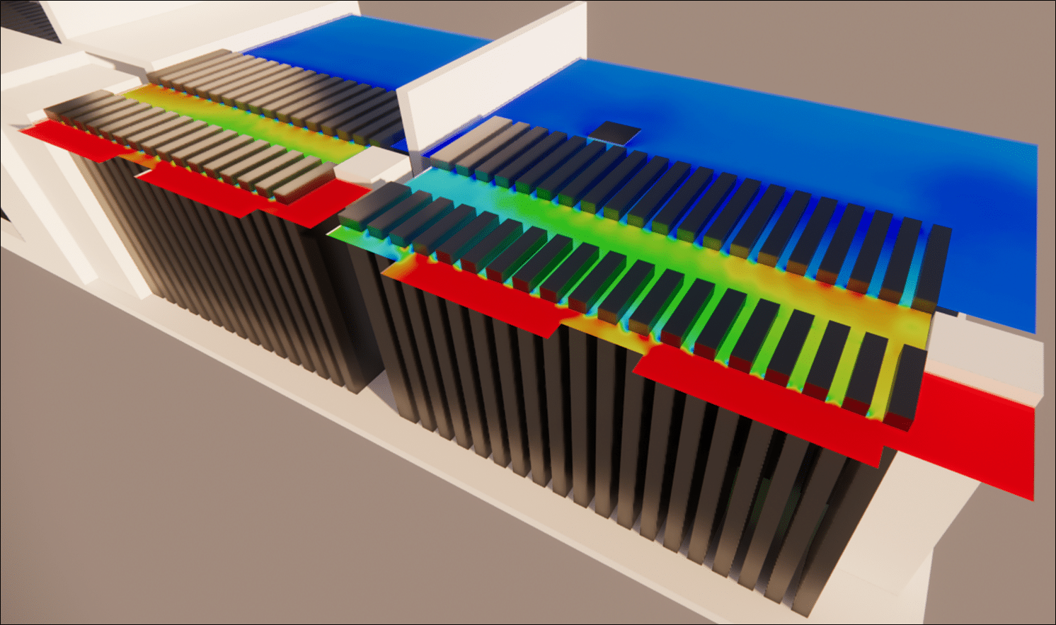
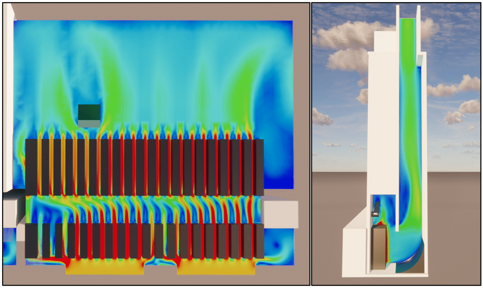
Air velocity and pressure studies
Impact of sound traps
Optimizing the design of GE ducts to limit pressure losses
The configuration of the premises led to excessive head losses. They were modified to reduce flow resistance, particularly at the sound traps and discharge duct. Deflectors were also installed to make changes of direction less abrupt.
Thanks to these modifications, pressure losses have been reduced by over 50%.
This reduction not only ensures efficient operation of the generators, but also allows higher air speeds at the duct outlet, thus reducing potential looping phenomena with rooftop air coolers.