Home » Industries » Production hall » Improving thermal comfort – Steelworks
Improving thermal comfort – Steelworks
Enhanced Operator Comfort: Thermal Analysis at Höganäs Belgium
EOLIOS carried out a thermo-aerodynamic audit of the Höganäs Belgium site.
Improving thermal comfort - Steelworks
Year
2023
Customer
Höganäs Belgium
Location
Ath - Belgium
Typology
Steelworks
Continue navigation :
Our other projects :
Latest news :
Heat dissipation improvement at Höganäs Belgium: Audit by EOLIOS
EOLIOS carried out a thermo-aerodynamic audit on the site of Höganäs Belgium, a company specializing in high-alloy powder metallurgy. The main aim of this study was tolower temperatures andimproveheatdissipation, with particular emphasis on the melting hall, where the two furnaces are located.
This initiative was designed to increase operator comfort throughout the production process. The central challenge of the project was to master the specific thermo-aerodynamic phenomena associated with the various manufacturing stages at extremely high temperatures.
On-site audit
Locate air entry points.
This audit studies ventilation and openings to identify the first possible improvements.
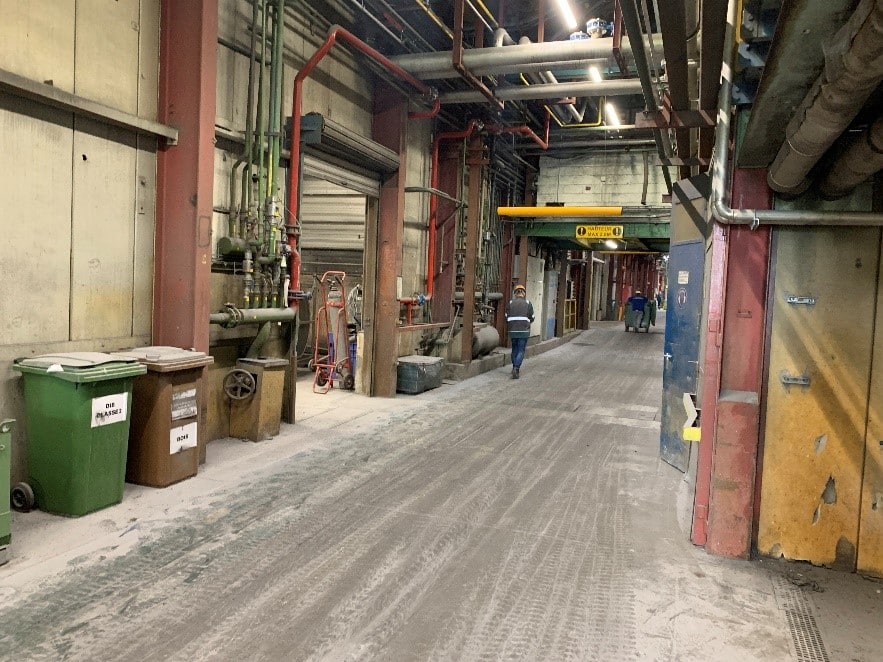
Two large doors at either end of the building are usually left open on the first floor, letting the air in. Another door, leading to the storage hall, is often open, allowing air to escape from the study area. All plant doors function as air inlets, causing significant fresh air infiltrationwhen open, which can lead todiscomfort in winter.
Air inlets are also present on the upper floor of the building, and to improve the comfort of technicians working close to the furnaces, several fans have been installed on the second floor.
Furnaces generate a lot of heat, which rises to the roof. To lower the temperature on the upper floors of the building, ventilators are placed on the roof, facilitating the evacuation of heat to the outside.
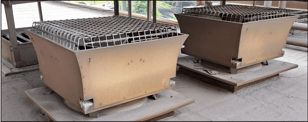
The roof is equipped with various natural air extraction devices.
Smoke tests carried out
A smoke test in an industrial building is a method used to assess thermal comfort and air quality inside the building.
To assess thermal comfort, smoke is used to visualize air movement and draughts inside the building. This detects areas with excessive draughts or air circulation problems, which can lead to uncomfortable temperature zones.
Smoke test around a furnace
As far as air quality is concerned, the smoke test can be used to demonstrate air flow patterns inside the building. It highlights unwanted air infiltration, leaks in the building envelope, leaks and ventilation problems. By visualizing the movement of the smoke, it is possible to identify areas where air is stagnant, where contaminants can accumulate and where ventilation is inadequate.
These tests enable EOLIOS engineers to identify potential problems related to thermal comfort and air quality, and to take the necessary steps to improve conditions inside the building. This may include adjustments to the heating, ventilation and air-conditioning system, repairs to improve the airtightness of the building, or changes to the configuration of the interior space to optimize air circulation.
Smoke test near an air intake
Smoke tests reveal various air circulation patterns in the building. Upstairs, the air flows out through the open windows, while some rises to the roof. In the vicinity of the fans, the warm air is drawn downwards, creating a homogenized temperature, albeit with an increase in heat in the lower areas.
Fans in the vicinity of ovens generate air movement, but are not conducive to better heat dissipation. In some areas, biflow occurs, with warm air rising to the extraction loops and cooler air flowing to the furnaces. Thermal stratification phenomena also occur, separating zones of warm and cold air.
Thermal camera study of the site
The aim of this section is to highlight the main sources of thermal phenomena and the areas that are more or less dense with heat. Thermal camera analyses are used to map hot and cold zones in support of numerical studies.
Thermal camera around a 5-ton furnace
Thermal camera of a melting furnace
CFD simulation
What is CFD simulation?
Computational Fluid Dynamics (CFD) is a numerical approach to analyzing fluid flows in a given environment, particularly in building design. It provides information on air velocities, pressures and temperatures in and around building spaces. This method uses partial differential equations to numerically solve the phenomena, taking into account boundary conditions such as building aeraulics, internal heat gains and air-conditioning systems. CFD simulations are essential for optimizing the ventilation and air conditioning of large spaces, guaranteeing optimum comfort.
Partial differential equations require boundary conditions to be solved. These are established on the basis of on-site measurement data and information from the project manager. For a steady-state study in a space open to the outside, we need to define the characteristics of the walls (material, physical properties, viscosity, temperature) as well as those of the surfaces exposed to the outside (flow direction, velocity, pressure, temperature, surface coefficients). It’s crucial to guarantee computational stability when defining these conditions, as the equations are solved iteratively to get closer to the solution.
The code solver used approximates the equations at each mesh node, respecting the fundamental principles of physics (conservation of mass and energy). It uses the standard k-epsilon turbulence model, which solves for two variables: turbulent kinetic energy and the kinetic energy dissipation rate. This model is widely used in industrial and HVAC applications because of its good convergence speed and acceptable memory requirements. For thermoaerulic studies, the effect of radiative exchanges between walls, thermal conduction, thermal draught and gravity are taken into account. The studies are carried out on the whole building, without establishing a symmetry section.
3D site model
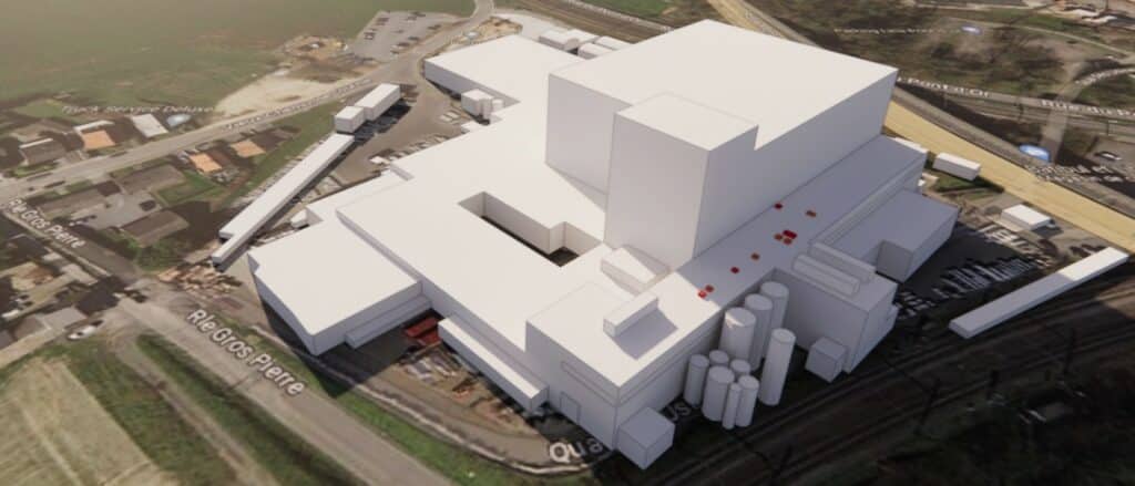
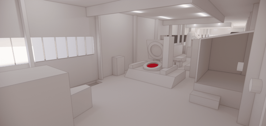
As part of the CFD study, the entire building was modeled to take into account the different aeraulic masks created by the site’s various modules.
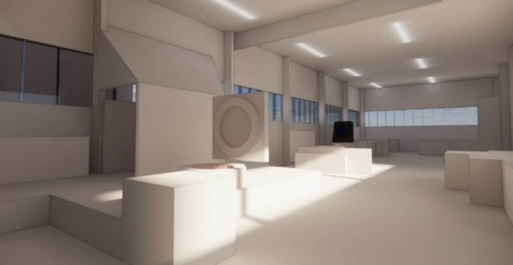
The furnaces and internal configuration of the melting building were modeled from site data, as were the fans and openings affecting air movement. The aim is to obtain an accurate representation of the complex air movements specific to these premises.
Simulation results
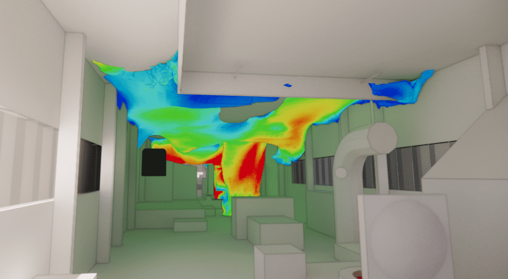
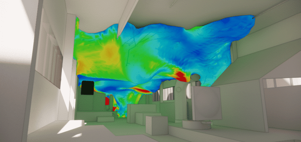
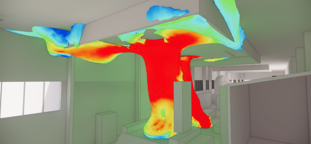
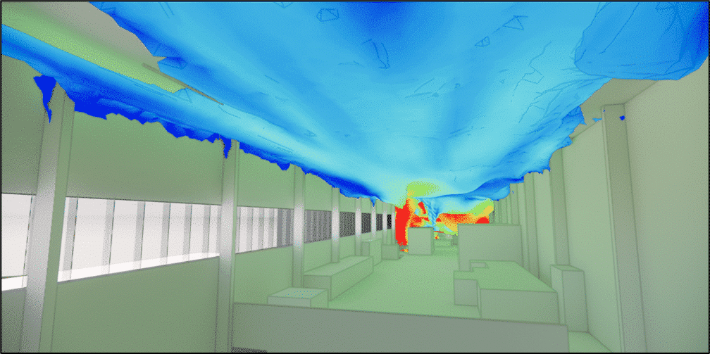
The aim of the studies was to highlight the thermal phenomena present on the site using two distinct scenarios: a baseline scenario with conditions similar to those of the audit, and another scenario with conditions allowing optimization of heat extraction.
The audit revealed that there was no heat buildup on the first floor, unlike the second floor, where furnaces and mold preheating generate high temperatures. It also revealed a lack of air extraction under the roof, preventing efficient heat dissipation.
An insulation study was carried out, recommending a suitable thickness of insulation. However, indoor temperature depends more on air movement and heat sources than on insulation.
The first scenario showed similarities with the audit, revealing separate air masses due to insufficient roof extraction.
The second scenario implemented new rooftop extraction systems and stopped the fans, significantly improving heat extraction, reducing heat diffusion and improving air quality. However, warmer zones persist around heat sources, suggesting a possible increase in the number of extraction systems.
Continue on this topic
Video summary of the study
Discover other projects
Simulation of saturated vapour capture on a continuous casting line
Simulation of saturated vapour capture on a continuous casting line
Radiation and ventilation study of an industrial ingot mould
Study of natural ventilation – Steelworks
Air quality improvement – Plant
Sizing – Chimney – Laboratory
High-temperature process plant
Natural ventilation – Metallurgy
Glassworks – Cognac
Natural ventilation – Aluminium Dunkerque
Smoke treatment system – CO2
VOC treatment process improvement
Sizing an industrial chimney – Furnace
Improving thermal comfort – Steelworks
Plant – Wind turbine
Industrial Workshop – Mexico
Factory – glove production
Stratification of a thermal storage tank
Generator sets – GE1
Glassworks – Hauts De France
Sizing of natural draft extractor hoods


