Home » Industries » Production hall » Natural ventilation – Aluminium Dunkerque
Natural ventilation – Aluminium Dunkerque
Analysis of Air and Heat Flows at the Dunkirk Aluminium Plant: 3D Modeling and CFD Simulations
The study focuses on optimizing the placement of ventilation systems for the Dunkirk aluminum plant. Numerical CFD simulations were carried out to analyze fluid flows and assess the plant’s aeraulic and thermal conditions, in order to propose precise recommendations for optimizing the placement of aeration systems.
Sizing of natural ventilation for the addition of a new furnace - Aluminium Dunkerque
Year
2024
Customer
Aluminium Dunkerque
Location
France
Typology
Industry
Continue navigation :
Our other projects :
Latest news :
Technical file :
Our expertise:
Study on the optimal placement of vents to improve thermal comfort at the Aluminium Dunkerque plant
Assessing the suitability of the ventilation system to support production expansion at the Aluminium Dunkerque plant
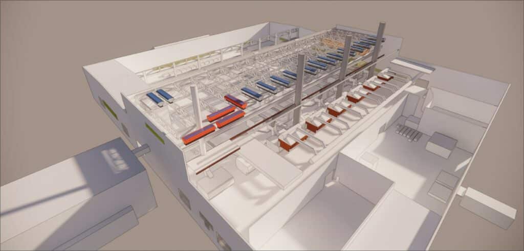
The study concerns the positioning of vents to improve thermal comfort at the Aluminium Dunkerque plant, which has a natural ventilation cooling system. The plant consists of 7 furnaces and an ingot production line, and to increase production capacity, the creation of an 8th furnace is envisaged. The temperature of these furnaces is in the region of 750°C, so significant hot air movements are generated inside the plant.
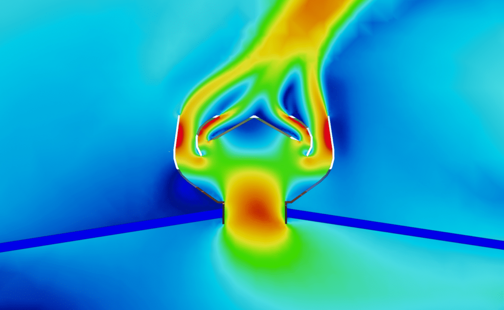
The foundry hall is equipped with 4 large carpenter aerators, 13 static aerators and louvers on some of the building’s facades. The aim of this study will therefore be todetermine whether the current aeration system is sufficient for the addition of an 8th furnace, and if not, how to remedy the situation.
Preliminary measurements for thermo-aerodynamic analysis
Use of smoke tests and temperature measurements to assess air circulation in the plant
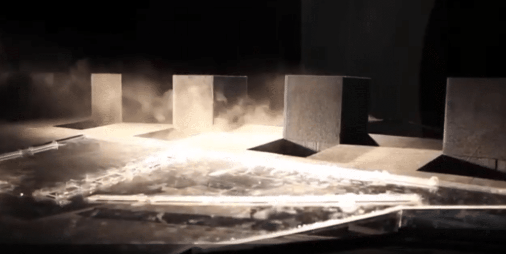
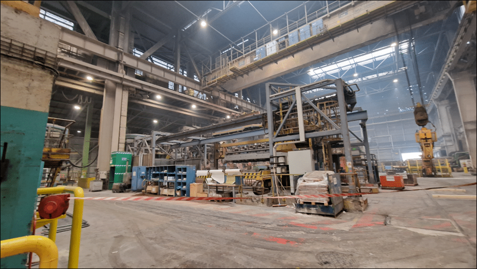
The aim of the audit was to gather as much information as possible about the site’s operation in terms of temperature and air movement. Various tests and measurement tools were used to achieve this objective. The smoke test was carried out using a smoke machine which generated a large quantity of smoke in the volume. This made it possible to visualize the macro movements of air currents within the site.
The fumes used were environmentally friendly and generated from a non-polluting glycol and water-based liquid. Videos were taken during these tests to analyze the phenomena observed on site. Air temperature measuring devices, such as telescopic probes under certified calibration, were used to record air temperatures and velocities on site. Smoke test results show that air currents in the vicinity of the furnaces are predominantly upward.
Smoke audit of systems
Thermal image analysis to identify heat sources
Thermal images were then used to highlight the main sources of thermal phenomena and the various zones of varying heat density.
The measured temperatures were compared with the results of the CFD simulations to verify their consistency.
The emissivity of the various surfaces was taken into account when estimating temperatures.
Integration of audit data for a faithful reproduction of the plant in simulations: Towards aeraulic and thermal optimization
All vents, openings and air passages on the site were identified during the audit. This allows the plant to be faithfully reproduced in simulations, also taking into account the plans supplied. Four types of opening were identified, including fully-open doors, façade vents, carpenter vents and static vents. The audit also identified the overall geometry of the foundry and the various volumes that influence airflow. This information on temperatures, air movements, openings and site geometry is essential for understanding and faithfully reproducing the plant in simulations. They will also serve as a basis for formulating recommendations aimed at optimizing aeraulic and thermal conditions on the site.
Weather analysis
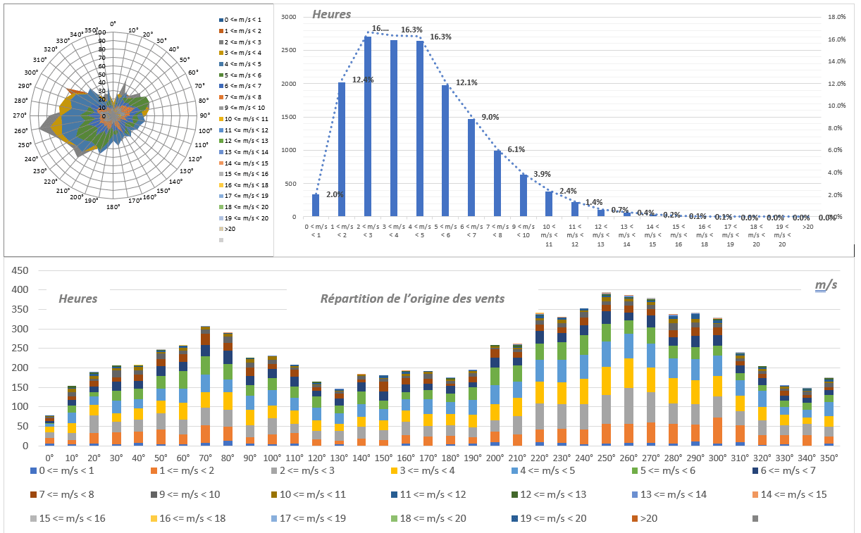
Climatological data from the Dunkirk meteorological station are of vital importance in defining the outdoor climatic conditions required to study the plant’s ventilation systems. Information collected includes wind speed and direction, as well as average minimum temperature in winter and average maximum temperature in summer.
In addition, the most extreme temperature peaks recorded are also taken into account. This data plays a crucial role in adapting ventilation and air-conditioning strategies to ensure optimum comfort for plant operators all year round.
CFD numerical simulation of thermal conditions in the plant
Creating a digital model
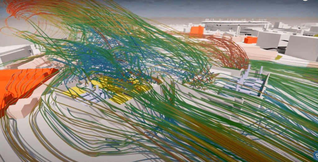
Computational Fluid Dynamics (CFD) is a numerical method for studying fluid flows in a given environment. This method uses partial differential equations to solve fluid flow problems, which are often analytically intractable.
In the context of buildings, a CFD study can provide information on air velocities, pressures and temperatures in and around building spaces. This provides a better understanding of aeraulic and thermal conditions, particularly when designing ventilation and air-conditioning systems.
CFD simulations are particularly useful for optimizing indoor comfort by ensuring that air flows are adequate and well distributed, thus helping to improve energy efficiency and occupant well-being. Geometric modeling is an essential step in CFD simulations. It consists in faithfully representing the geometry of the site or building under study. This makes it possible to define boundary conditions such as wall types, surfaces open to the outside, internal heat gains, etc. Geometric modeling also simplifies the model by eliminating elements that are irrelevant to the aeraulic and thermal study, making it easier to interpret the results.
In short, CFD simulations are used to study fluid flows in building design. Theyoptimize aeraulic and thermal conditions,enhance indoor comfort andoptimize energy efficiency. Geometric modeling and model meshing are key steps in this process, as are the definition of boundary conditions and the use of appropriate turbulence models.
Simulation results
Strategic positioning of air extraction systems: the key to optimum airflow performance
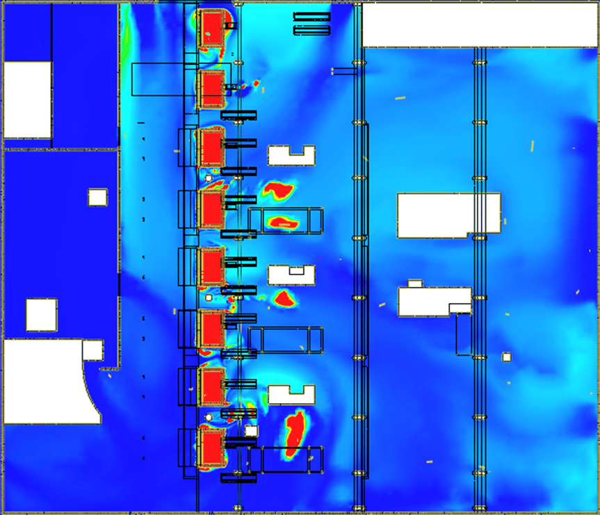
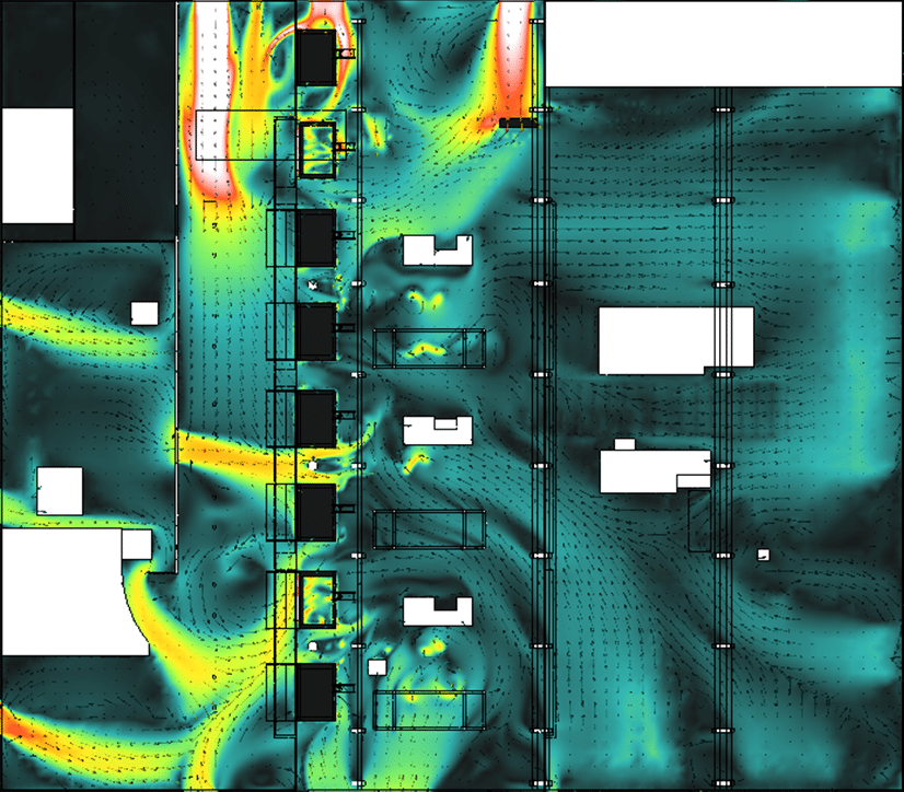
Theaim of this study was to verify the site’s airflow performance following the addition of the new furnace 8. Several scenarios were examined to this end. The first scenario was the existing scenario, using the air extraction systems as they are currently in place, with external conditions based on meteorological analysis. However, the results showed an imbalance in temperature distribution between the north and south sides of the site, due to the absence of an extraction hood for kiln 8 and a carpenter’s ventilator. The second scenario incorporated additional statics above furnace 8. The results showed that theaddition of these aerators enabled more rapid and targeted evacuation of heat-laden air, thus improving the site’s aeraulic operation.
The importance of the correct placement of ventilation openings: strategy for efficient thermal draft and optimum hot air evacuation
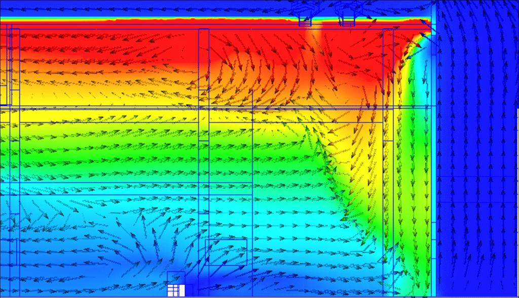
Following the results of the second scenario, the third scenario was studied, involving the closure of a ventelle deemed counterproductive. This scenario showed that closing this opening favored stratification of warm air, resulting in better thermal draft and more efficient evacuation of heat-laden air. These results demonstrate the importance of the correct placement of air extraction systems and ventilation openings in the proper aeraulic functioning of the site. The resulting recommendations encourage the addition of targeted vents to facilitate more efficient evacuation of heat-laden air, and the closing of certain openings to promote optimal stratification of warm air.
Dust and pollutant distribution study
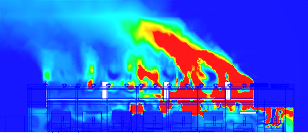
In this study, two configurations were examined to assess the effectiveness of dust extraction in the case of furnace 8 in open door mode. The first configuration was the basic one, while the second involved adding static aerators and closing the inappropriate ventelle.
Impact of different types of static aerator
The simulations then included the installation of a new carpenter aerator above furnace 8. Simulation results showed that the newly added carpenter aerator had a significant impact on air flows. The flow directed from furnace 8 to the small carpenter aerators already present disappears.
In terms of temperature distribution, the results show a distribution similar to that of the previous scenarios, but with a clear drop in temperature under the roof thanks to the presence of the carpenter aerator.
The temperature under the roof thanks torapid evacuation of warm air charged with calories by the carpenter aerator. The results also show that the total extraction rate remains globally constantwith a slight increase compared with the existing configuration. These results demonstrate the effectiveness of the carpenter aerator added above furnace 8 for rapidly evacuate calorie-laden hot air. This modification therefore contributes to improve airflow and thermal conditions in the building.
Furnace radiation study
Impact of different types of static aerator
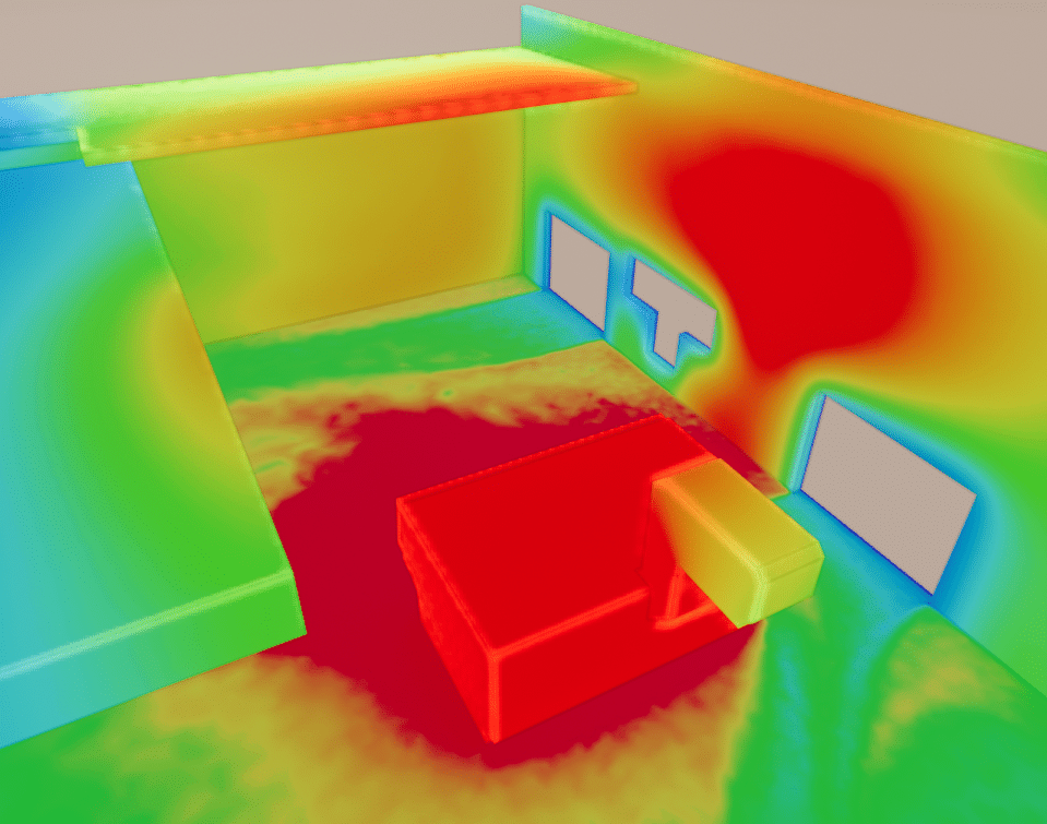
The radiative study as part of the thermo-aerodynamic analysis of a plant provides a better understanding of the impact of thermal radiation, assesses the interaction between radiation and convection, and identifies areas where adjustments are needed to optimize thermal conditions inside the plant. This improves worker comfort, prevents overheating problems andoptimizes the plant’senergy efficiency.
Simulations were therefore carried out to assess the radiative transfer from furnace 8 to the surrounding walls in two different scenarios. The first scenario corresponds to the usual configuration where furnace 8 is closed. The results showed that significant radiative fluxes were received by the north façade, the wall facing the furnace and the lower roof, with maximum temperatures reaching around 70°C. The second scenario concerns open furnace 8, with an internal temperature of 500°C to take into account the cooling of the open furnace. The same zones are then also subject to significant radiative flux, with maximum temperatures of around 75°C.
These results demonstrate thesignificant impact of radiative transfer from Furnace 8 to the surrounding walls. They highlight the areas receiving the greatest radiative flux, notably the north façade, the wall facing furnace 8 and the lower roof.
Summary of plant thermo-aerodynamic analysis
Analysis of thermal conditions: Identification of risk zones and recommendations for improving worker comfort
Our company’s expertise enabled us to find technical solutions for the addition of a new furnace in the plant, and toimprove thermal comfort for workers. The modifications carried out resulted in a significant reduction in temperatures under the roof and in the work areas, as well asimproved ventilation by reducing the flow of hot air to specific locations.
Theradiative analysis also identified three areas where radiative transfer is more intense, potentially posing a hazard to workers. These results contribute to a better understanding of air flows and thermal conditions, and enable us to make recommendations for optimizing ventilation, temperature and, more generally, working conditions inside the site.
Continue on this topic
Video summary of the study
Summary of the study
The study focused on the optimum placement of vents to improve thermal comfort at the Aluminium Dunkerque plant, which uses a natural ventilation cooling system. The aim is to determine whether the current aeration system is sufficient for the addition of an 8th furnace and, if so, to propose solutions.
Various preliminary measurements were carried out, such as smoke tests to observe air movements, temperature measurements and thermal images to identify heat sources. These data were used to create a 3D model of the plant in which numerical CFD simulations were carried out.
CFD simulations are used to study fluid flows and simulate the plant ‘s aeraulic and thermal conditions. The results showed that the addition of certain aerators would enable faster, more targeted evacuation of hot air, thus improving the site’s aeraulic operation.
In conclusion, this study enabled us to determine the optimum placement of vents to improve thermal comfort at the Aluminium Dunkerque plant, with a view to adding an 8th furnace. The results of the CFD simulations provided precise recommendations for optimizing energy efficiency and the well-being of plant operators.
Video summary of the mission
Discover other projects
Simulation of saturated vapour capture on a continuous casting line
Simulation of saturated vapour capture on a continuous casting line
Radiation and ventilation study of an industrial ingot mould
Study of natural ventilation – Steelworks
Air quality improvement – Plant
Sizing – Chimney – Laboratory
High-temperature process plant
Natural ventilation – Metallurgy
Glassworks – Cognac
Natural ventilation – Aluminium Dunkerque
Smoke treatment system – CO2
VOC treatment process improvement
Sizing an industrial chimney – Furnace
Improving thermal comfort – Steelworks
Plant – Wind turbine
Industrial Workshop – Mexico
Factory – glove production
Stratification of a thermal storage tank
Generator sets – GE1
Glassworks – Hauts De France
Sizing of natural draft extractor hoods

