Accueil » Data center » External CFD simulation for data centers » Data Center – PA 22 – External
Data Center – PA 22 – External
Study of thermal plumes in a data center
Eolios used CFD modeling to study the thermal and aeraulic exchanges of a data center in Meudon. The study enabled us to understand and optimize the cooling of high-density IT equipment. Recommendations were made to improve airflow in the event of specific wind conditions. Thanks to this study, suitable solutions have been proposed to guarantee reliable results and save design time and costs.
Data Center - PA 22 - External
Year
2024
Customer
NC
Location
France
Typology
Data center
Continue browsing :
Our other projects :
Latest news:
Our expertise:
CFD study of thermal and aeraulic exchanges in a Data Center in Meudon, France
Eolios' technological expertise: Modeling heat exchange in a data center
EOLIOS ingénierie, one of Europe’s leading providers of CFD modeling for data centers, contributed its technical expertise in understanding and modeling the heat and air exchanges outside a data center in France, in relation to the heat release from generators and rooftop systems, by carrying out CFD studies.
In the very large-scale data center environment, cooling system standards capable of meeting the evolving needs of the IT industry are required due to theincreasing density of IT equipment (over 10 kW / rack). Cooling to remove heat from high-density IT equipment is a key consideration for data centers. These calories are evacuated by a series of systems placed in high concentration on the roof.
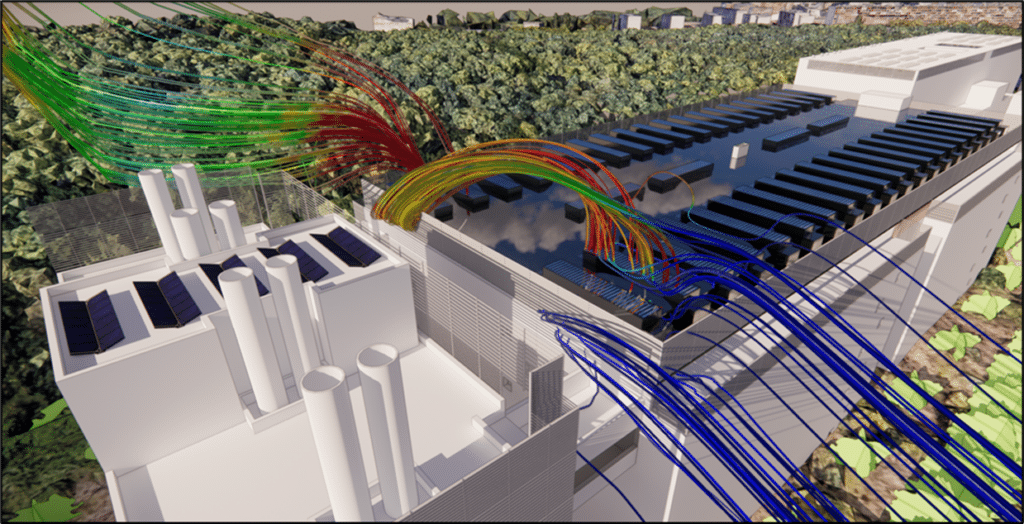
This study examines the exhaust plume from a series of generators for a data center. The aim is toanalyze the system used to improve air mixing in air coolers located on the roof of technical rooms occupied by generators, to ensure that thermal exhaust from these systems cannot contaminate the supply air through looping. System looping can lead to loss of power to the air coolers. This loss of power causes a rise in temperature in the data halls, which in turn can lead to data hall failures.
To achieve this, our EOLIOS engineers used CFD numerical calculations to simulate the thermo-aerodynamic behavior of the various phenomena taking place outside the model.
A multitude of parameters were taken into account by our experts: radiant wall temperatures, thermal draft from manufacturing processes, wind pressure, internal resistance to vertical airflow; location and flow resistance characteristics of envelope openings; local terrain and the immediate impact of the building structure on the wind; and the presence of mechanical systems stirring air around processes.
A meteorological study was carried out to determine the usual climatic conditions around the site. It revealed that the wind is constant throughout the year, with a dominant south-westerly flow and temporary north-easterly phenomena. The study was carried out for an outside temperature of 40°C and a wind speed of 4 m/s, the most prevalent wind speed on site and unfavorable because it is likely to draw the thermal plume from the generators down onto the roof systems.
Creation of a Digital Twin for a Data Center Studied in CFD
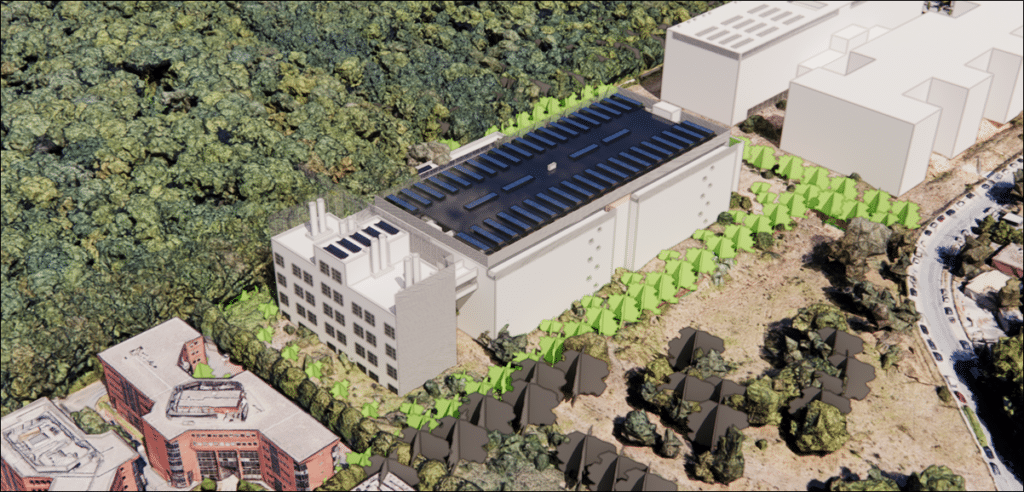
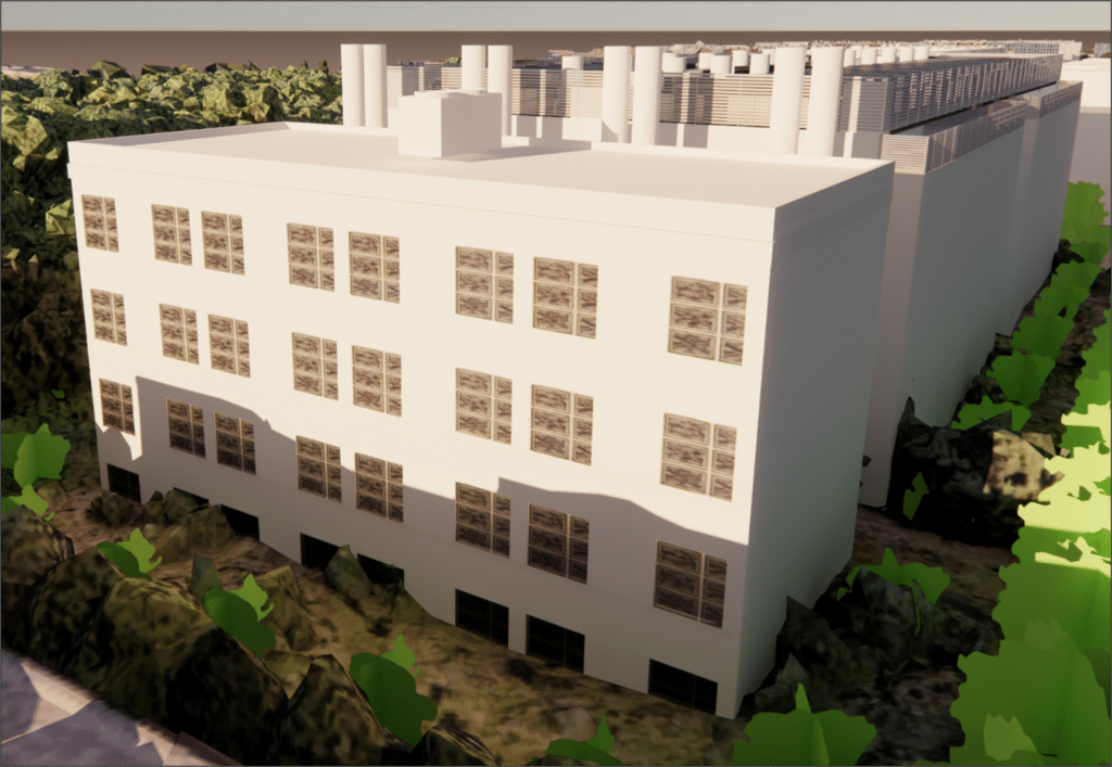
The digital twin of the data center, created by Eolios for a CFD study, uses the simplified geometry of the site and its surroundings within a 400m radius for a more precise analysis of the evolution of the thermal plume according to wind directions. This study is part of a process to improve the design of the building, due to areas of over-temperature in suction, leading to an update by Eolios engineers for a new model. The digital twin includes the generator sets, substation, chimneys and roof-mounted air coolers. Mechanical louvers are installed around the roof and generators. The information required for the study of all the systems is taken from their technical data sheets.
The generators are housed in custom-built concrete units incorporating all the necessary technical equipment. Chimneys have been modeled on the roof toevacuate noxious gases from the generator engines. These noxious gases can be harmful to the environment and human health, making it necessary to exhaust them through a chimney or pipe. The engine exhaust stack can be installed either outside or inside the building.
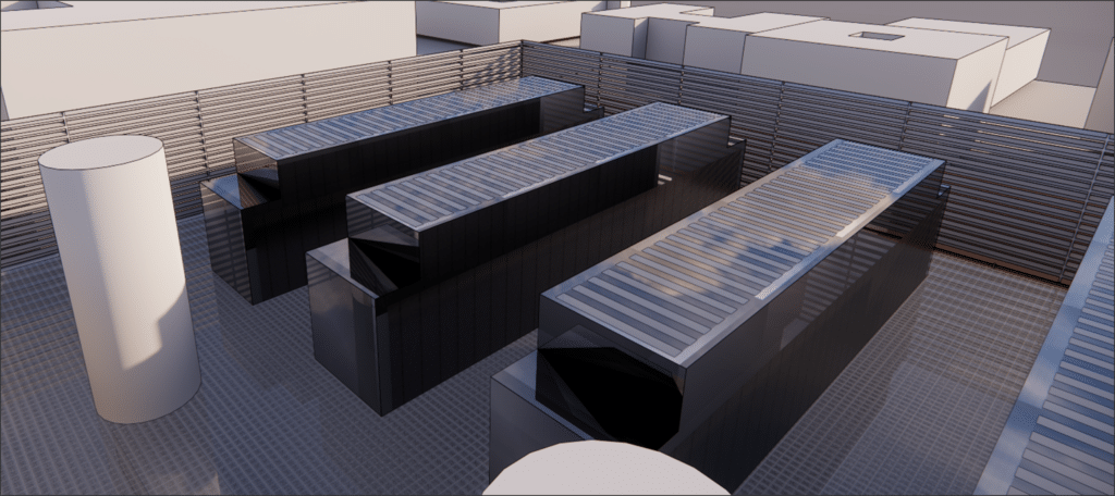
Roof-mounted air coolers dissipate the heat generated in the data halls. They are equipped with mufflers.
Capture of external thermo-aerodynamic phenomena
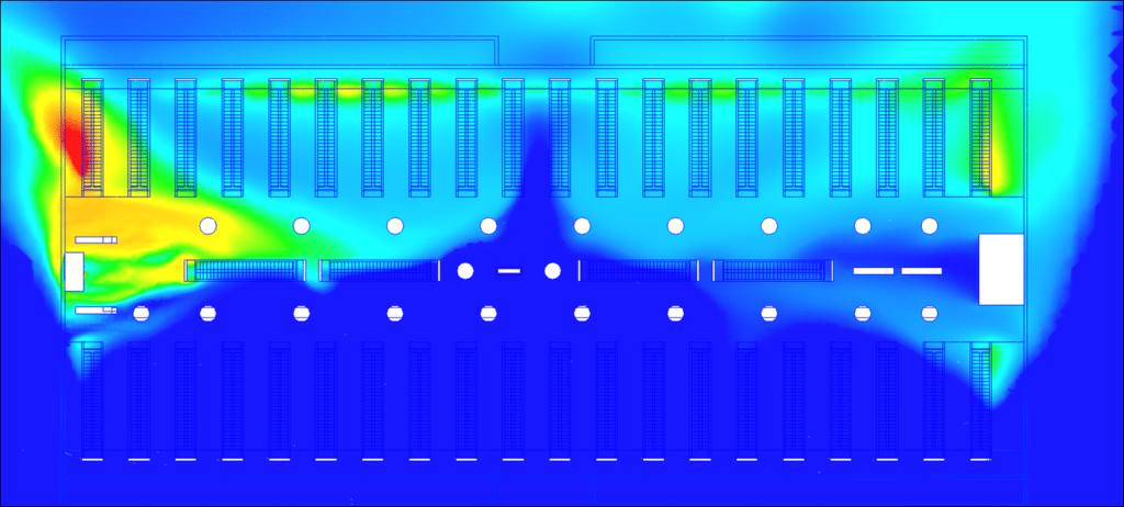
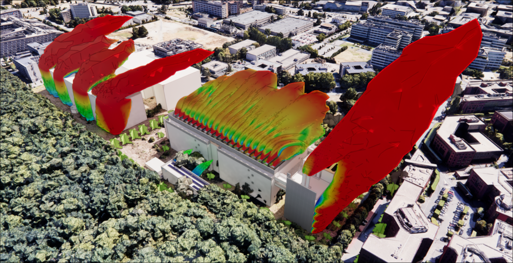
CFD simulation has shown that the temperature generally remains below 45°C. Higher temperature zones have been identified, attributable to the looping of the air coolers on the north side to those on the south side when the wind is from the north-east, and vice versa when the wind is from the south-west. In fact, some of the air discharged by a row of air coolers seeps under the roof through the open ends and is then re-sucked by the air coolers in the same row, resulting in higher temperatures at the system intake.
However, this temperature increase is very localized, occurring only in the air cooler closest to the generators, and remains below the temperature target.
In addition, numerical simulation has confirmed that thermal plumes from generators, exhaust stacks, intake/discharge grilles and the electrical transformer substation do not represent a problem for rooftop systems.
This study highlighted the fact that the high density of rooftop installations leads to looping phenomena, resulting in a local increase in air temperature. However, this phenomenon does not jeopardize the durability of the installations.
Eolios engineers have also produced a rough model of PA13. The main thermo-aerodynamic characteristics revealed significant looping problems that could compromise the long-term viability of the installations. It has been observed that thermal plumes from generators are significantly sucked back by roof air coolers.
CFD study recommendation
We strongly recommend carrying out an aeraulic check of this data center for a north-easterly wind.
The conclusions of our study, carried out by our engineers, identified these problems and proposed appropriate solutions to the design teams. The use of CFD simulation makes it possible to analyze, verify and correct any errors in the design. This fast, precise method saves design time and costs, while ensuring concrete, reliable results. Integrating CFD right from the design phase is a guarantee of avoiding any future problems by calling in experts to ensure the viability of the project.


