Cooling by evaporation: efficient, but under watch
Cooling towers (TAR) reject the heat of air-conditioning and process installations to the outside. Their principle — cooling water by evaporation — is remarkably efficient, but it comes with the dispersion of a plume of warm, humid air laden with fine droplets.
This plume crystallises three inseparable issues: a health risk (legionella), a strict regulatory framework (ICPE) and an airflow challenge (recirculation). All three are addressed together.
What is a cooling tower?
A cooling tower is a piece of equipment that removes the heat from a water circuit by bringing it into contact with an airflow. In a wet cooling tower, part of the water evaporates: it is this change of state that delivers highly efficient cooling, but generates an aerosol plume.
The main types are:
Open wet circuit
- The circuit water is in direct contact with the air.
- Very efficient, but the highest health risk.
Closed wet circuit
- The circuit is isolated; the spray water runs over the outside.
- A good performance / risk-control compromise.
Dry / hybrid circuit
- Exchange without evaporation (or partial).
- Lower risk, but less efficient in hot weather.
The legionella risk
The warm, stagnant water of cooling towers offers a favourable environment for the growth of legionella, bacteria that, dispersed into the air as aerosols, can cause a serious lung infection: legionnaires' disease.
The danger is not the water itself but the micro-droplets carried by the plume, which can be inhaled at a distance. Hence a twofold requirement: controlling proliferation (treatment, maintenance, monitoring) and preventing the plume from being re-inhaled — in particular via the fresh-air intakes of the building and the neighbourhood.
Dedicated resource: legionnaires' disease and cooling towersThe ICPE regulatory framework (heading 2921)
In France, cooling installations that disperse water into an airflow fall under heading 2921 of the nomenclature of installations classified for environmental protection (ICPE). Depending on the thermal power rejected, the installation is subject to declaration or registration.
The framework requires, among other things, a methodical risk analysis (MRA) of legionella proliferation and dispersion, a maintenance and monitoring plan, and periodic inspections. The siting and control of the plume dispersion are an integral part of this safety demonstration.
Compliance is not limited to maintenance
Cooling-tower regulations are often thought of through the lens of water treatment. But the demonstration of risk control also includes the airflow: proving that the plume does not return towards the air intakes or the occupied zones. This is where simulation provides quantified proof.
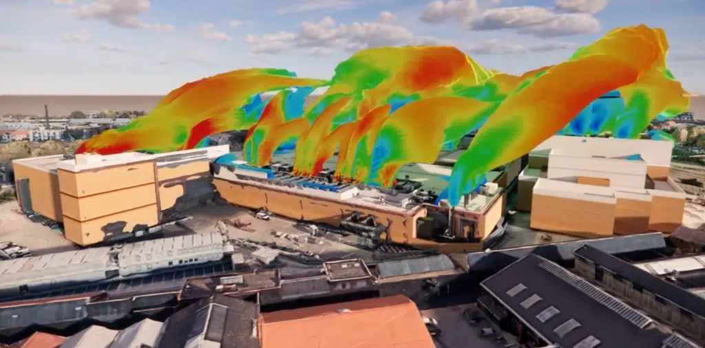
Plume recirculation: the real airflow challenge
The plume rejected by a cooling tower is warm and humid. Depending on the wind, the terrain and the neighbouring buildings, it can:
Recirculate to the tower
- The plume returns to the tower's intake: the air drawn in is already warm and humid.
- Consequence: loss of performance and over-consumption.
Reach the air intakes
- The plume is re-inhaled by the fresh-air intakes of the building or the neighbourhood.
- Consequence: health risk and non-compliance.
These two phenomena depend finely on the site geometry, the discharge height, the ejection velocity and the wind conditions. Flat-rate distance rules are not enough to guarantee against them.
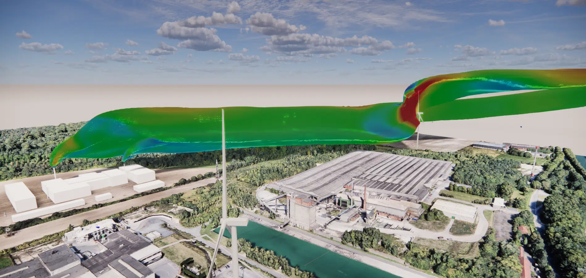
The diagnosis through CFD simulation
CFD simulation models the tower's discharge, the site and its surroundings, then computes the plume trajectory and its dilution for each wind condition. This makes it possible to verify, in a quantified way:
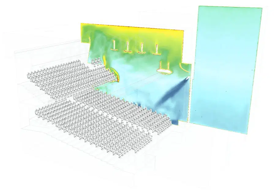
Non-recirculation
- Concentration and temperature of the air drawn in by the tower.
- Performance margin in the worst conditions.
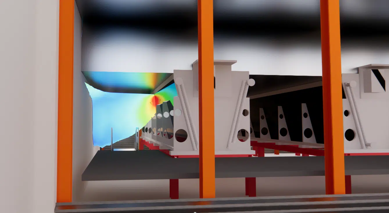
Protection of the air intakes
- Plume dilution at the fresh-air intakes and sensitive zones.
- Compliance with the health and regulatory objectives.
Prevent and site well
From the diagnosis, the installation is optimised through concrete levers:
| Lever | Effect |
|---|---|
| Discharge height | Raising the discharge point moves the plume away from the air intakes and low zones. |
| Ejection velocity | A sufficient velocity propels the plume higher and accelerates its dilution. |
| Orientation & position | Account for the prevailing winds and the layout of the neighbouring buildings. |
| Distances to air intakes | Move and protect the fresh-air inlets away from the fall-out zones. |
Our engineers simulate the plume dispersion and demonstrate risk control for your ICPE file. Let's talk.