Calculate pressure drops and hydraulic resistances
The energy loss in the flow of a fluid is related to the viscosity of the liquid, but the viscosity itself is not the only factor determining the pressure drop. But it can be argued that the magnitude of the pressure drop is almost always proportional to the square of the mean fluid velocity.
This hypothesis is confirmed by the results of most of the experimental work and specially staged experiments. For this reason, pressure losses are usually calculated as a function of the velocity load (specific kinetic energy of the flow). So:
Naturally, the solid walls prevent the free flow of liquid. Therefore, with the relative movement of fluid and solid surfaces, hydraulic resistances inevitably appear. Some of the flow energy is expended to overcome the resulting resistance.
This loss of energy is called hydraulic energy loss or head losses. Hydraulic losses are primarily associated with exceeding the frictional forces in the flow and depend on a number of factors, the main ones being:
The geometric shape of the pipe
The speed of the fluid
The roughness of the solid walls of the flow
The type of flow
The viscosity of the liquid
Some other operational properties of the liquid
Lhydraulic losses are practically independent of the pressure in the liquid.
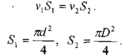
If we consider a pipe with two cross-sections 1 and 2 with the same а cross-sectional area, the difference in levelling height Z1 and Z2the specific energy loss can be considered as
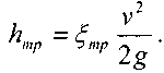
Experiments show that in many cases the energy losses are directly proportional to the square of the fluid flow rate, so in hydraulics it is usual to express the energy lost as fractions of the kinetic energy attributed to the unit weight of the liquid.
Where Ɛ̧ is the coefficient of friction.
Thus, the drag coefficient can be defined as the ratio of the lost height to the velocity height.
Singular head losses on local hydraulic resistances
Singular hydraulic resistance
Local hydraulic resistances are all sections of the hydraulic system where there are bends, obstacles, expansion or contraction, causing a sudden change in the flow profile. Examples of local resistances may be bends in the pipe axis, changes in the cross-sectional areas of any hydraulic apparatus, pipe joints, etc.
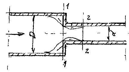
Sudden widening of a pipe:
Sudden channel expansion can often be observed at the junction of pipeline sections. The value of the pressure drop coefficient is determined with sufficient accuracy at the theoretical level.
Liquid flowing through a pipe of smaller diameter d, falling into a pipe of larger diameter, does not immediately touch the walls of the new pipe section, but only in a cross section of 2-2′.
In the area between sections 1 – G and 2-2′, a zone is formed in which the liquid hardly participates in the movement through the pipes, forming a local vortex flow, where it undergoes deformation. For this reason, some of the kinetic energy of the moving fluid is expended to maintain the “parasitic” melting and deformation of the liquid. The values of the average liquid velocities in the sections can be determined from the continuity condition.
Thus, we can say that the height loss during an abrupt flow expansion is equal to the velocity height corresponding to the lost velocity.
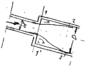
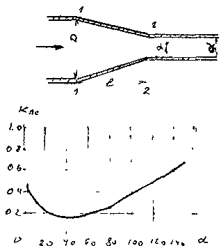
Smooth expansion of a pipe (diffuser):
The smooth expansion of the pipe is called a diffuser. The flow of fluid through the diffuser is complex. As the live cross-section of the flow gradually increases, the fluid velocity decreases accordingly and the pressure increases.
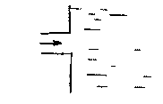
Sudden pipe narrowing:
With a sudden narrowing of the channel, the liquid flow becomes detached from the walls.
In this flow region, two intense vortex formation zones are formed (both in a wide pipe section and in a narrow section), which gives rise, as in the previous case, to the appearance of pressure losses. This is made up of two components (friction losses and shrinkage losses).
Smooth pipe narrowing
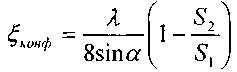
The smooth narrowing of the canal is achieved with a tapered section called a confuser. The head losses in the confusor are formed almost due to friction, as vortex formation in the confusor is practically absent. The pressure drop coefficient in the confusor can be determined by the formula
For a large cone angle> 50°, the pressure drop coefficient can be determined by introducing a correction coefficient km into the formula.
Normal hose inlet
From the tanks where the liquids are stored, the inlet of the discharge pipeline is carried out in the so-called normal version, i.e. when the axis of the pipeline branch pipe is normally located on the side wall of the tank. This type of hydraulic resistance can also be attributed to the resistances associated with the change in channel size. The dimensions of the new channel are infinitesimal compared to the dimensions of the original channel with the cross section of the reservoir.
In this case, inside the jet bypass pipe, the liquid flowing from the tank fills the entire section of the pipe not immediately, but only at a certain distance from the inlet. In the stagnant zone, a part of the liquid performs a rotational movement and the vortex thus created generates additional g.
The pressure drop ratio is about half the velocity head: Ɛ̧ = 0.5
Pipe outlet in a liquid at rest
It is a common element in the connection of the pressure part of the pipeline with the tank. The pipeline inlet pipe is normally located on the side wall of the tank. This type of hydraulic resistance can also be considered as a kind of sudden expansion of the fluid flow to an infinitely large section. The value of the pressure drop coefficient, in most cases, is considered to be equal to a velocity head.
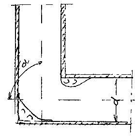
90° rectangular elbow
Under such hydraulic resistance, we will understand the place of connection of pipelines of the same diameter, to which the center lines of the pipelines do not coincide, so they form a certain angle between them. This angle is called the angle of rotation of the channel, because here the direction of movement of the liquid changes. The physical basis of the process of conversion of kinetic energy during the rotation of the flow is quite complex and should only be considered as the result of these processes. Thus, during the passage, a complex flow form with two zones of vortex fluid movement is formed. It should be noted that this elbow as a connection element is extremely undesirable due to the high pressure drop in this type of connection.
Smooth rotation of the channels
This type of hydraulic resistance can be considered more economically favorable in terms of the magnitude of pressure losses, because in this case there are practically no dangerous areas for the formation of an intense fluid movement. Nevertheless, under the influence of the fact that when the flow is rotated, centrifugal forces appear which contribute to the separation of the liquid particles from the pipe wall, vortex zones always appear. In addition, in this case, there are backflows of liquid directed from the inner wall of the pipe to the outer wall of the pipe.
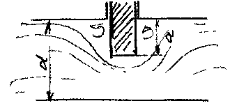
Valve
Gate valves are often used as a means of controlling the flow characteristics of the fluid (flow rate, head, velocity). If there is a valve in the pipeline, the flow around the valve slows down greatly. This flow leads to the appearance of vortices near the valve dies. The pressure drop coefficient depends on the degree of closure of the valve: a/d
Register
Gate valves are often used as a means of controlling the flow characteristics of the fluid (flow rate, head, velocity). If there is a valve in the pipeline, the flow around the valve slows down greatly. This flow leads to the appearance of vortices near the valve dies. The pressure drop coefficient depends on the degree of closure of the valve
Check valves and filters
Head loss coefficients are usually determined experimentally.