Simulation of wind pressure on buildings – Eurocode 1


Home » Air & Wind » Simulation of wind pressure on buildings – Eurocode 1
Study the impact of wind on the structure of your buildings
EOLIOS carries out CFD studies to assess aerodynamic loads on buildings.
- Calculating pressure coefficients
- Structural impact study
- Load calculations for curtain walls
- Study of critical failure scenarios
- Eurocodes
- Street furniture wind resistance
- High-rise buildings
- Wind noise study
- Study of maximum inlet pressure for air treatment systems
High winds: a complex and dangerous structural action
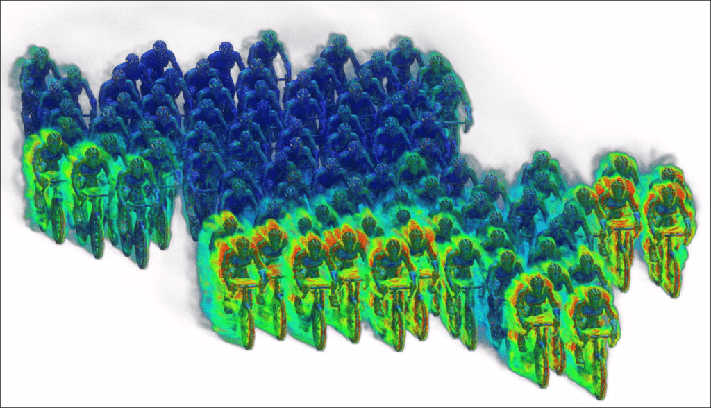
Wind action on buildings is intrinsically three-dimensional and highly context-dependent. High winds generate aerodynamic loads that can affect not only the load-bearing structure, but also the building envelope, technical equipment, fastening systems and external fittings.
Beyond global forces, local effects are the main risk factor. The combination of height, geometry (sharp angles, recesses, complex roofs), porous facades and the surrounding environment (obstacles, other buildings, relief, etc.) generates advanced aerodynamic phenomena: intense overpressure and depressions, high pressure gradients, local wind accelerations, Venturi effects between built volumes, corner vortices and unstable recirculation zones.
These phenomena can lead to extreme stresses in very localized areas, often poorly represented by global normative methods. In dense urban environments, interactions between buildings amplify these effects, making wind assessment particularly sensitive to calculation assumptions.
Misunderstanding these mechanisms can lead to :
- local undersizing of facade or roof elements,
- removal of technical equipment,
- risks for users in exposed pedestrian areas,
- premature deterioration of the structures and high repair costs.
Controlling the effects of wind is therefore a key factor in the project’s safety, sustainability and economic viability.
CFD: an advanced engineering tool for wind risk management
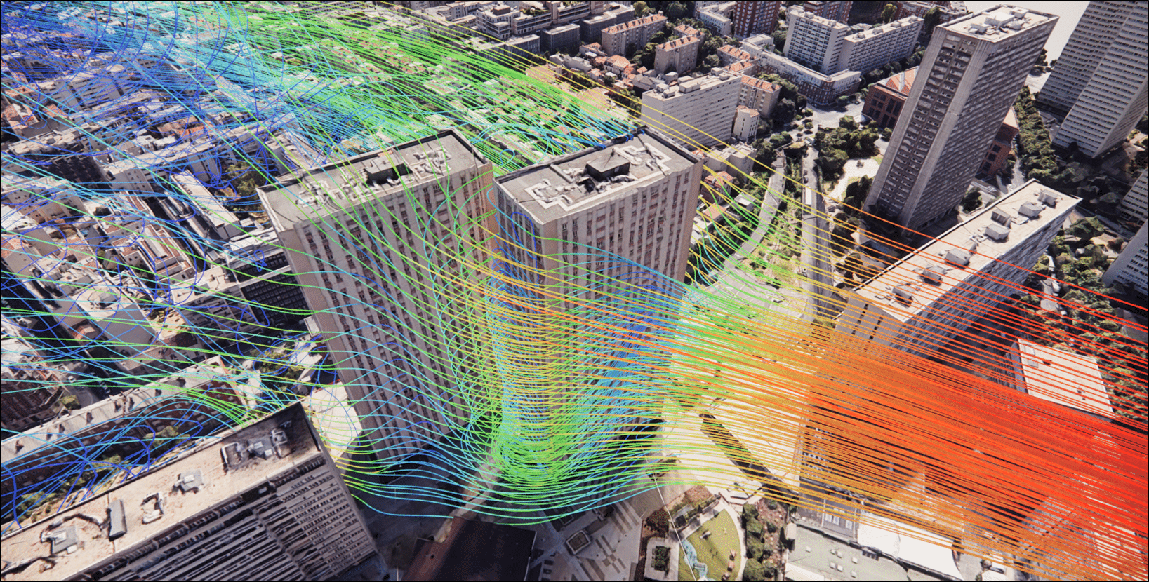
Numerical flow simulation (CFD) provides a realistic physical approach to wind action, going beyond the limits of simplified normative methods. It offers a three-dimensional, local and continuous representation of air flows around buildings, integrating the real geometry of the project and its immediate environment.
CFD not only enables us to quantify stresses, but above all to understand the physical mechanisms behind these stresses. This understanding is decisive in guiding design choices, adjusting architectural shapes, positioning equipment and defining appropriate constructive solutions.
Local and directional analysis of solicitations
Unlike approaches based on average Eurocode coefficients, CFD allows :
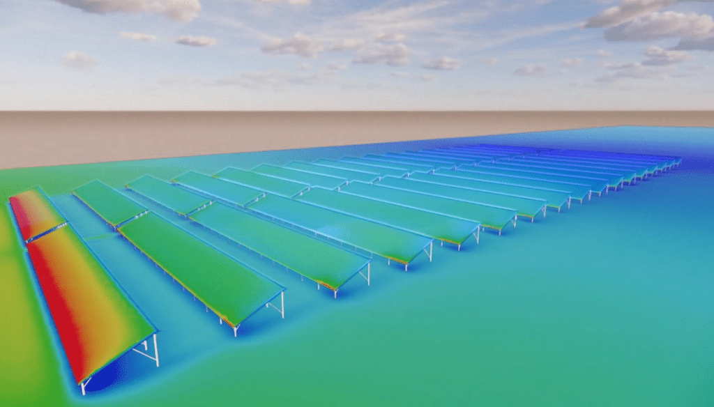
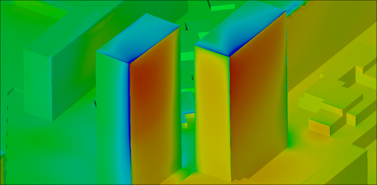
- precisely map pressures and depressions on all walls,
- identify areas of pressure peaks due to corner and edge effects,
- analyze local wind accelerations and shear zones,
- characterize aerodynamic interactions between neighboring buildings.
This local approach is particularly relevant for high-rise buildings, unconventional architectural forms, dense urban projects and sites subject to strong prevailing winds.

Design-integrated decision support
When CFD is integrated into the upstream phase, it becomes a genuine design tool. It can be used to compare different variants (layout, massing, orientation, screens, windbreaks),optimize the sizing of exposed elements, and provide technical justification for the choices made in dealings with inspection bodies and insurers.
Experience shows that early integration of CFD significantly reduces the risk of subsequent rework and the associated additional costs.
A controlled standards framework: rigorous integration of Eurocode 1
The studies carried out by EOLIOS fall strictly within the normative framework ofEurocode 1 – Wind Actions (NF EN 1991-1-4) and its National Annex. This document is an indispensable tool for the design of wind-resistant buildings.
CFD is not used here as an alternative to standards, but as a complementary, coherent and justifiable tool.
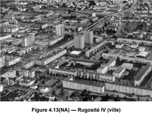
Terrain features
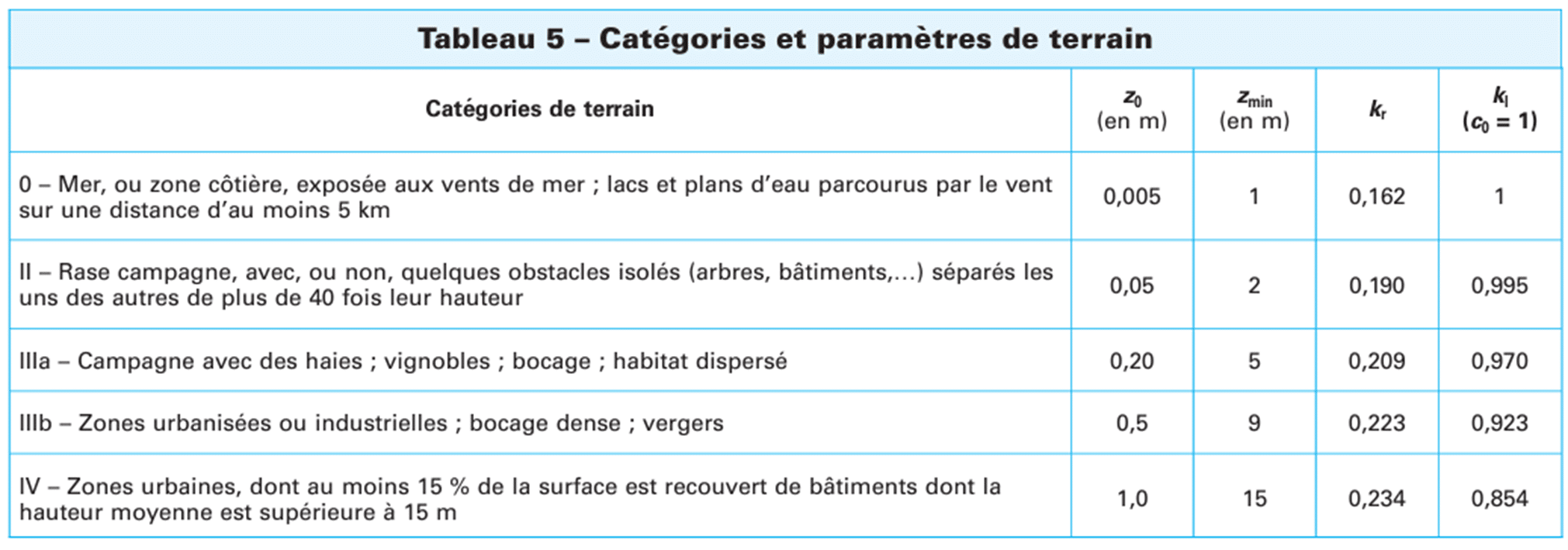
The table below, taken from the national appendix to the Eurocode, gives the values of z0(apparent roughness height) according to the nature of the site. In the case of urban studies, the roughness required for calculations corresponds to type IV urban roughness.
This roughness directly conditions the wind speed profile, a fundamental element in defining the input conditions for the CFD model.
Definition of reference speed
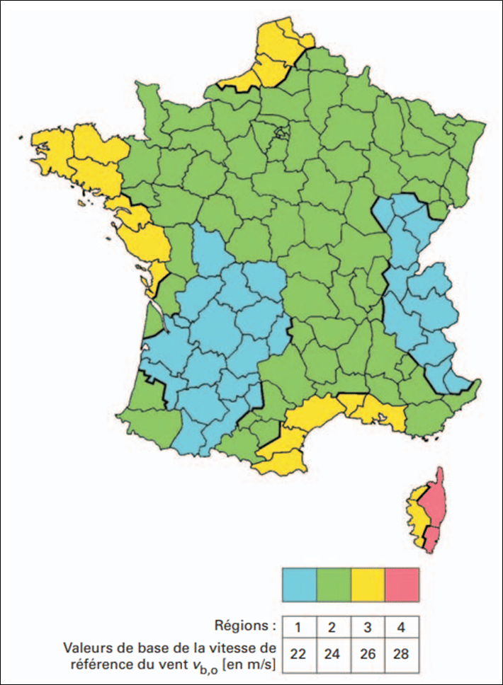
The base speed vb,0 corresponds to an extreme but rare wind event (mean return period of around 50). This speed is defined over a period of 10 minutes at 10 m above ground level in a rural area. It is therefore dependent on the geographical area, and is therefore defined by Eurocode zoning.
The base velocity vb,0 can be corrected according to the specific context of the project by using 2 representative coefficients in order to constitute the reference velocity vb:
- The direction coefficientcdir: This takes account of the fact that the strongest winds do not always blow in the most unfavorable direction. In other words, it can be used to reduce the reference speed when critical wind directions are unlikely.
- Season coefficient cseason: This takes into account the fact that extreme winds do not occur regularly throughout the year. For permanent structures, the coefficient retains a value of 1 (max). On the other hand, for temporary structures such as scaffolding, the coefficient can take on a lower value.
In this way, the reference speed can be corrected as follows:
Vb =cdir x cseason x vb,0
Orographic coefficient c0 (z)
The orographic coefficient takes into account theinfluence of terrain relief (hills, ridges, escarpments) on wind speed. The effects of orography can be neglected if the average windward slope of the terrain is less than 3°, in which caseco(z)=1.
Roughness coefficient cr (z)
TheCr(z) roughness coefficient takes into account the apparent roughness of terrain (buildings, trees, towns) to calculate the average variation in speed as a function of altitude. It is obtained from an equation whose parameters are :
- z0 the roughness length of the terrain category used
- zmin the lower limit of validity of the logarithmic aspect of the roughness coefficient
- zmax the maximum height of the study area
- kr the terrain factor
The roughness coefficient is then governed by the following equation:
Cr(z) = kr*ln(z/z0) for zmin ≤ z ≤ zmax
Cr(z) =Cr(zmin) for z ≤ zmin
Average speed
The average velocity Vm(z), takes into account the reference velocity Vb and the apparent roughness parameters associated with category IV terrain. It is calculated in accordance with the Eurocode using the following formula:
Vm (z) = Vb *Cr(z) *Co(z)
By iterating this equation, it is then possible to obtain a logarithmic speed profile.
Gusty winds
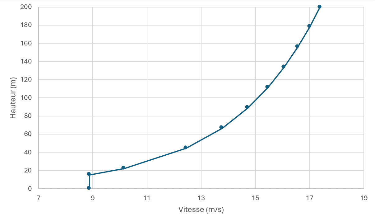
Once the average wind speed profile has been determined, it is then possible to calculate the maximum gust speed profile for the project. This takes into account theturbulent intensity and temporal variability of the wind. This profile is obtained using the following formula:
Vr(z) = sqrt[1+7*kl/ln(z/z0)]*Vm(z)
Where z represents the height, z0 the roughness length of the terrain category under consideration, kl the turbulence coefficient of the terrain category under consideration and Vm(z) the mean velocity determined above.
A second velocity profile is then produced. This will serve as adomain input for future simulations.
CFD modeling: a robust, controlled approach
Reconstruction of the built environment
The study area is modeled over a perimeter sufficient to guarantee the complete development of flows. Surrounding buildings are integrated to capture masking, channelling and aerodynamic interaction effects.
Geometric simplifications are carried out in a controlled manner to preserve the physical mechanisms while ensuring the numerical stability of the calculations.

Atmospheric boundary layer modeling
Wind can be described by the notion of an atmospheric boundary layer, which breaks down into 3 sub-layers:
- The outer layer, or inertial sub-layer, is about a kilometer thick (varying from 0.5 to 3km).
- The surface boundary layer, 10 to 100m thick. It represents around 10% of the thickness of the atmospheric boundary layer. It is the locus of significant gradients in wind speed and temperature. Wind direction remains relatively constant with height.
- The rough sub-layer, a few metres thick. Flows here are three-dimensional, disordered and strongly affected by obstacles.
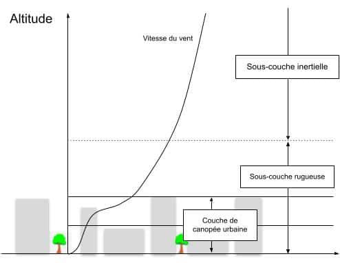
On the ground, the wind is slowed by obstacles and ground roughness. Above the ground, in the undisturbed geostrophic wind layers (around 5 km high), the wind is no longer influenced by the state of the Earth’s surface. Between these two layers, wind speed changes with ground altitude, following a logarithmic profile. This phenomenon is known as vertical wind shear.
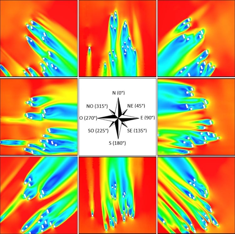
Multi-case directional analysis
Simulations are carried out for the eight main directions of the wind rose, corresponding to an extreme gust wind according to Eurocode 1. This multi-case approach makes it possible to identify the most penalizing orientations and characterize directional site effects.
The values of intermediate directions (NNE, NEE, SEE, etc.) can be estimated by linear interpolation of the nearest simulated directions.
Advanced results processing and validation
Physical analysis and expert interpretation
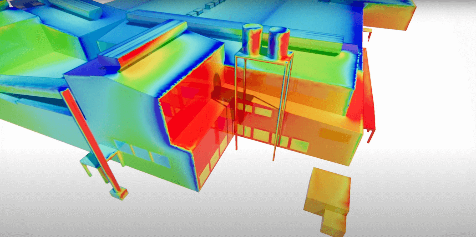
EOLIOS’ expertise lies in the physical interpretation of flows. Simulations enable us to pinpoint the origin of pressure peaks, understand their mechanisms (stall, vortex/structure interaction, channeling) and propose optimization levers.
Deliverables include :
- pressure maps and pressure coefficients,
- comparative directional analyses,
- identification of critical areas,
- design recommendations.
CFD enables detailed data analysis for both simple and complex geometries, and three-dimensional identification of stresses and site effects.
Cross-reference with Eurocode analytical approach
To validate the calculations performed. It is possible to carry out analytical calculations according to the Eurocode on largely simplified geometries in order to provide an order of magnitude of the dimensions.
In fact, the Eurocode can be used to calculate an estimate of the peak dynamic pressure, which can then be used to establish average values for aerodynamic pressure on the faces by coupling the peak dynamic pressure with standard pressure coefficients specific to the various building faces, available in the Eurocode abacuses.
Peak dynamic pressure can be calculated using the following formula:
qp(z) = [1 + 7 *Iv(z)] * 0.5 * ρ * vm(z)2
Furthermore, for h> 2b with h the height of the tower and b the length of its base in the perpendicular wind direction, qp(z)=qp(h) is assumed for h-b < z < h. For z > h-b:
qp = [1 + 7 *Iv(h)] * 0.5 * ρ * vm(h)2
The pressure coefficient varies according to the size of the surface being considered. Its maximum value is cpe,1, the pressure coefficient for a surface A<1m2, which in practice allows the calculation of small fasteners.
Eurocode abacuses provide these pressure coefficients as a function of the geometry encountered.
Finally, the maximum 1m2 averaged pressure is determined from the following formula: P = qp*cpe.
Expertise for controlled projects
EOLIOS combines a thorough understanding of regulatory requirements, advanced CFD expertise and the ability to physically interpret results, to help its customers secure and optimize their projects in the face of wind-related risks.
CFD thus becomes a strategic tool for risk reduction, technical justification and economic control, at the service of safe, sustainable, high-performance buildings.
Why supplement the Eurocode with a CFD study?
Eurocode 1 provides an indispensable normative framework for assessing wind actions, based on idealized geometries and global coefficients. It guarantees regulatory compliance, but reaches its limits as soon as the project is set in a complex real-life context.
CFD simulation makes it possible to overcome these limits by integrating :
- the actual geometry of the building (complex shapes, recesses, angles, atypical roofs),
- theurban environment and site effects (neighbouring buildings, masks, urban canyons, Venturi effects),
- local and directional stress analysis, highlighting pressure peaks and critical zones,
- detailed consideration of turbulence and gusts, essential for sizing sensitive elements.
Combined with the Eurocode, CFD becomes a decision-making engineering tool, making it possible to secure design choices, technically justify sizing assumptions and limit the risks of local undersizing or over-conservatism.
Find out more: