Home » High-temperature process plant
High-temperature process plant
Analysis of Air and Heat Flows in a Plant with High-Temperature Processes: 3D Modeling and CFD Simulations
Theaim of this study is to verify and improve the design of the thermal control system of a plant located in Canada, using CFD numerical modeling.
The aim is to understand and control the specific thermo-aerodynamic phenomena induced by the various manufacturing stages of an innovative process involving high-temperature furnaces.

High-temperature process plant
Year
2024
Customer
NC
Location
Canada
Typology
Industry
Continue:
Our other projects :
Latest news :
Technical files :
Our expertise:

Using numerical simulation for thermal optimization
Thermo-aerodynamic and energy optimization using CFD simulation
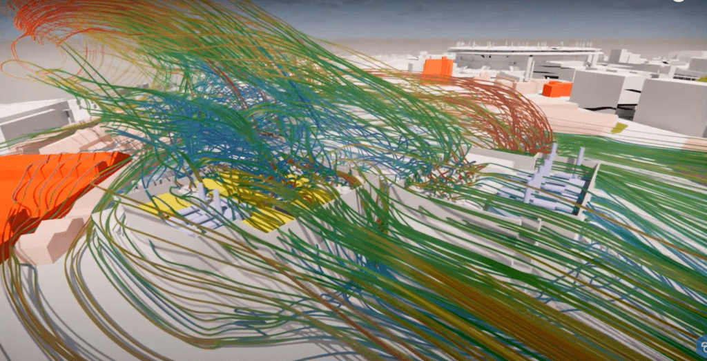
Simulations were carried out using CFD (Computational Fluid Dynamics), a method for analyzing and predicting the movements of fluids such as air. This virtual approach simulates thermo-aerodynamic phenomena in the plant, taking into account interactions between different surfaces, heat sources and air flows. Thanks to CFD, flows and temperatures can be visualized and analyzed in detail, contributing to a better understanding of processes and optimizing plant performance and safety.
CFD simulations are particularly useful for studying the design of ventilation and air-conditioning systems in large spaces such as auditoriums, to ensure that air inlets and outlets ventilate the auditorium correctly and provide optimum comfort for each spectator.
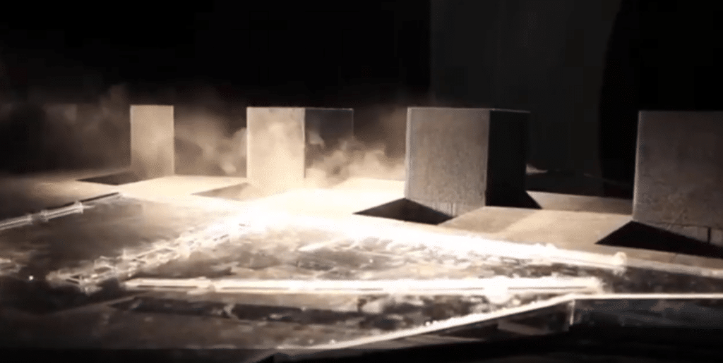
Plant modeling
Geometric modeling is a key step in CFD simulations. It enables us to accurately represent the geometry of the site or building under study, and to define boundary conditions such as walls, openings to the outside, and internal heat gains. Geometric modeling also simplifies the model by eliminating irrelevant elements, making it easier to interpret the results.
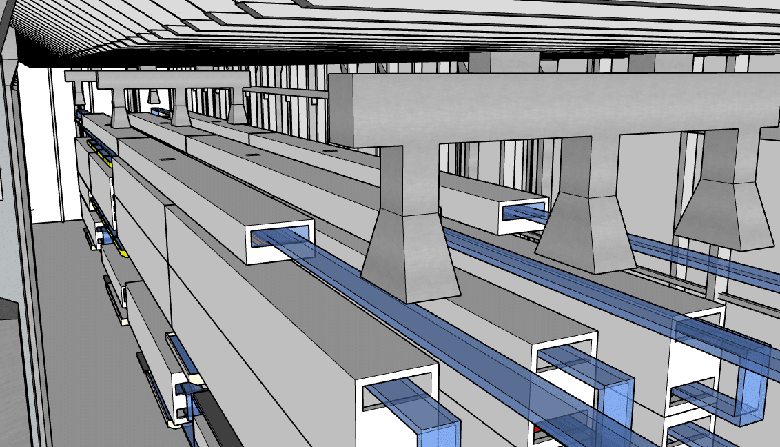
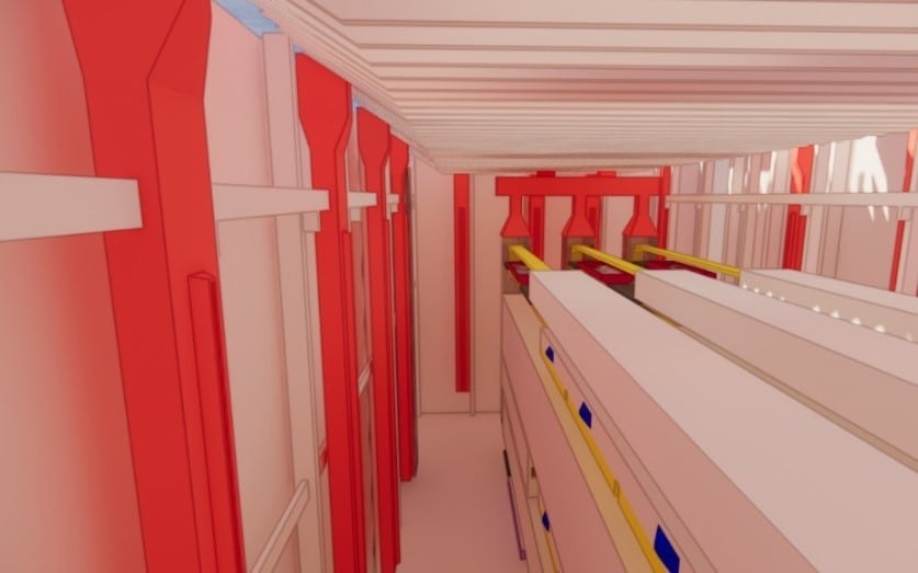
To create the 3D model of the plant, all the plant’s air volumes and walls in contact with the outside world were taken into account. All surrounding rooms are taken into account in the simulation, so as to take into account the heat transfers taking place between different rooms. A study of the geometry and environment was therefore carried out to take into account all thermal bridges resulting from the performance of the materials, constituting a target value to be distinguished from the simulated value taking into account the inevitable imperfections of installation.
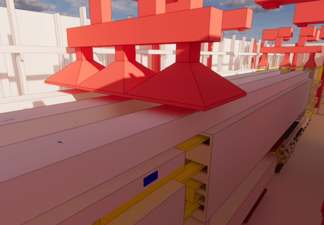
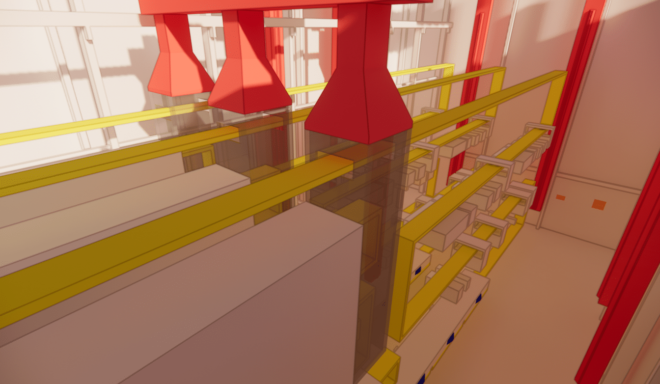
The production chain, including certain processes, has been modeled, in particular the furnaces present. The air-conditioning distribution systems in the production hall were also modeled, including the supply and exhaust ceiling fans.
Three louvers are also present high up on the west façade. These louvers are sheathed along the entire height of the wall, so that outside air enters the factory from below. The windscreens are open in summer and winter.
The temperatures, powers and flows generated by the production line’s machines were also taken into account. In addition, since ventilation system operation depends on outdoor conditions, which can vary between -23°C in winter and 32°C in summer, the study was carried out over these two seasons.
Simulation results for summer operation
First, numerical simulations were carried out for summer operation, the most critical case due to high temperatures. All heat-generating systems were considered at the maximum temperature of their temperature range. The outdoor temperature taken into account is 32°C, and solar gains are taken into account.
Detection of specific thermal anomalies
Numerical simulation has highlighted the fact that, on the whole, temperatures are correct in the environment and the HVAC system is fairly well dimensioned for the process.
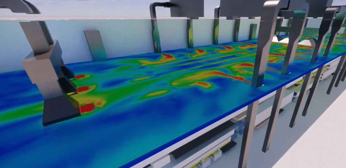
Indeed, the air movements generated by the nozzles cause air to circulate throughout the space, including between the production lines, at a speed of around 0.5 m/s, ensuring good air circulation and homogeneous temperatures.
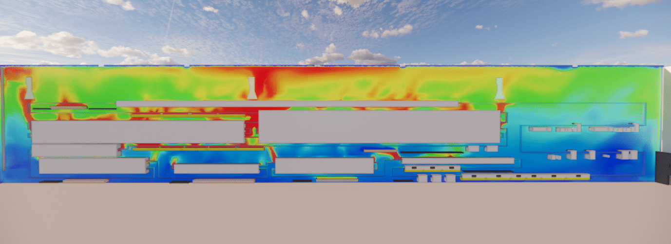
Ambient temperatures vary overall from 36°C to 42°C depending on the height of the production lines, so there is a delta of around 10°C in the worst case with the supply temperature.
However, under the roof, some of the heat-laden air has difficulty being evacuated, and temperatures can reach 50°C.
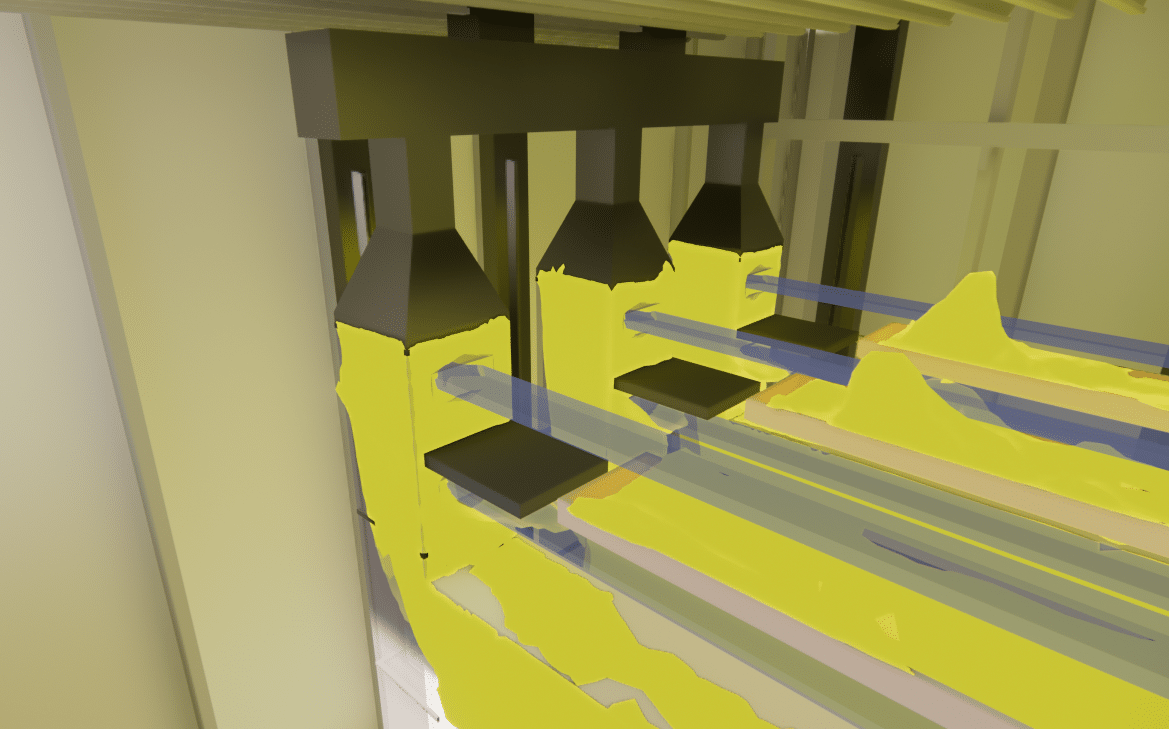
In this configuration, the nozzles on the north side are in line with the extraction hoods, creating a bypass that diverts hot air away from the main furnaces.
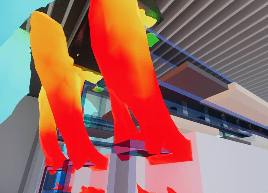

In the central section, the hoods are too close to the upper wall of the end ovens, so their suction is disrupted, and some of the hot air from the main ovens is not drawn in and stagnates under the roof.
What’s more, not all hood intake surfaces are large enough for the size of the thermal plumes coming out of the ovens.
Solutions for optimum thermal management
Following this initial simulation, EOLIOS recommended moving the air ducts on the north wall to blow in more strategic directions, so as not to disrupt their localized suction. It was also recommended to remove the nozzles from the last 2 m of the supply ducts. The cold air blown in at this height will be taken up directly by the aspirators, generating a bypass, and will not be used to cool the atmosphere below.
The EOLIOS teams also worked on the size of the extractor hoods, so as to eliminate the space between two hoods, and/or, where possible, to partition off the oven outlet and the hoods, particularly for the ovens in the North and South sections. This crossover does not need to be hermetically sealed, and the presence of glove openings is not a problem– it’s just a matter of guiding the thermal plumes coming out of the furnaces.
Improvements brought by the new configuration
Simulation has shown that the partitioning ensures that the heat released by the furnace at the end of the production line is not dispersed into the environment. By moving the supply ducts to the north and reducing the maximum height at which nozzles can be installed on the supply ducts, fresh air can be better distributed to important areas.
Increased hood suction surfaces in the central part of the furnace enable better capture of the thermal plumes emerging from the central openings of the main furnaces.
The results of this simulation show ambient temperatures ranging from 35°C to 40°C at production line level, depending on height, and temperatures between 41°C and 45°C under the roof, with peaks reaching 50°C in the central part. Temperatures at all points in the room are about 2°C (3.6°F) lower than in the existing design.
Despite this new design, a small amount of the heat-laden air still has difficulty being evacuated to the central part. However, the volume of air involved is smaller than in the previous design. One solution could be to change the hood fans in the central section to increase the suction flow rate, and compensate by increasing the delivery flow rate of the MUA systems that were previously reduced. Another solution would be to install a partition in the central area, if possible.
Numerical simulation in winter with proposed improvements
Identification of condensation risks
In this case, the outdoor temperature considered is the lowest for a winter day. Calories generated by the system and surrounding rooms are considered at the minimum of their temperature range. The simulation results show that, despite the shutdown of both supply air systems, the air is still moving at all points in the room, and there are no problematic dead zones.
Room temperatures vary from 15°C at floor level to 20°C on the top floor of the production line. Roof temperatures vary between 20°C and 25°C overall, with peaks of around 30°C in the central and northern parts of the building. These temperature peaks are due to the reduced suction capacity of the hoods in winter.
However, very cold temperatures are reached at the louvers. This louver blows indoor air at a temperature below 0°C, cooling the room considerably and creating discomfort for workers passing by.
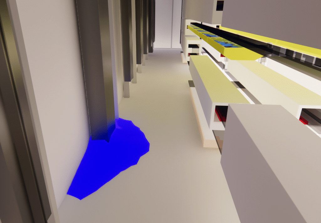
We’ve been able to recommend closing this louver when the outside temperature is very low to avoid these problems. On the other hand, the design of the plant’s thermal control system in winter conditions appears to be well suited to overcoming low temperatures: the temperature is homogeneous throughout the building, and blowing reaches all the important zones in the room.
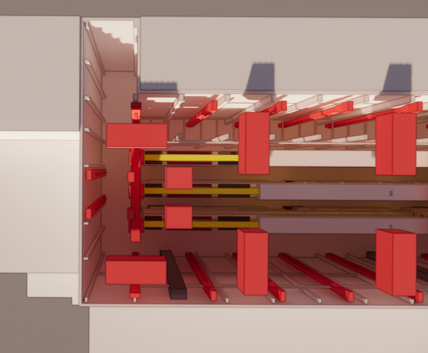
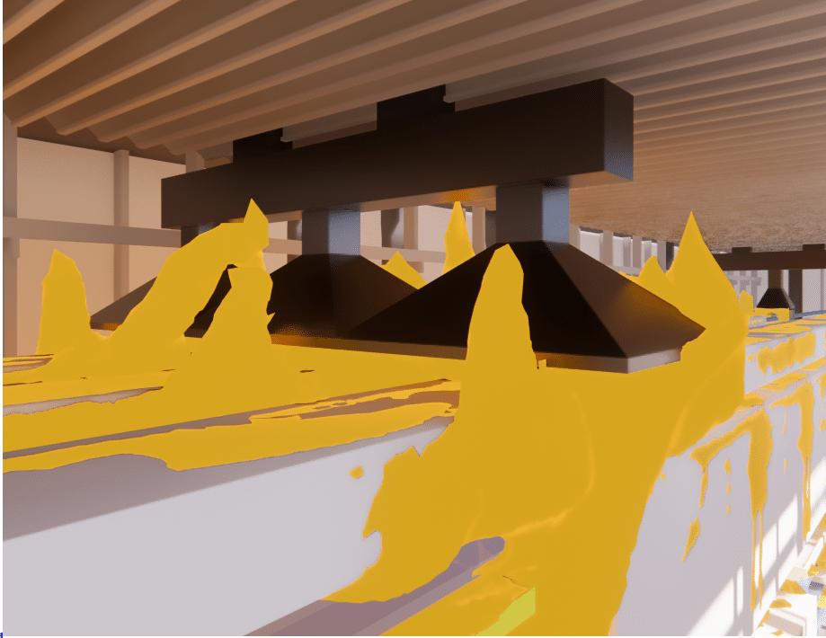
Study of the dispersion of pollutants generated by tanks
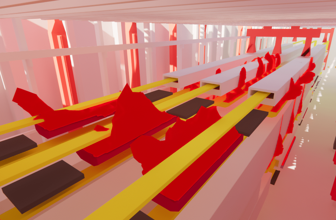
A pollutant dispersion study was carried out for the summer situation without the hoods over the pre- and post-wash tanks.
This study shows that the hoods located above the acid tanks at the start of the production line capture all the emissions generated.
Furthermore, it appears thatsome of the emissions generated by the pre- and post-wash tanks are less well evacuated, and are therefore likely to stagnate under the roof in the low-speed zone located under the fans in the northern part of the building.
Following the results of the second scenario, the third scenario was studied, involving the closure of a ventelle deemed counterproductive. This scenario showed that closing this opening favored stratification of warm air, resulting in better thermal draft and more efficient evacuation of heat-laden air. These results demonstrate the importance of the correct placement of air extraction systems and ventilation openings in the proper aeraulic functioning of the site. The resulting recommendations encourage the addition of targeted vents to facilitate more efficient evacuation of heat-laden air, and the closing of certain openings to promote optimal stratification of warm air.
Summary of plant thermo-aerodynamic analysis
Analysis of thermal conditions: Identification of risk zones and recommendations for improving worker comfort
EOLIOS ingénierie contributed its expertise in fluid mechanics to characterize and improve the air conditioning system in the production room of a glove factory.
A new design has been proposed to allow better heat extraction in summer and better distribution of fresh air in important areas.
Continue on this topic
Video summary of the study
Summary of the study
The study concerns the thermal control system of a plant, using CFD numerical modeling. The aim is to study this system and check how it works, with a view to improving it in the future.
This study is based on 4 main principles: optimizing outside air diffusion, understanding seasonal temperature distribution, assessing operator thermal comfort, and studying pollutant evacuation. It is concentrated solely in the production room.
Various numerical simulations were carried out to study fluid flows and simulate the plant’s thermal and aeraulic conditions. They highlighted a number of areas for improvement, which led Eolios engineers to propose a new configuration involving modifications to the hoods, air ducts and nozzles.
The improvements have resulted in better heat extraction in summer and improved distribution of fresh air in key areas.
Mission video summary - CFD plant simulation
Discover other industrial projects
Glassworks – Cognac
CFD study of compressors on an offshore vessel
Simulation of saturated vapour capture on a continuous casting line
Simulation of saturated vapour capture on a continuous casting line
Radiation and ventilation study of an industrial ingot mould
Study of natural ventilation – Steelworks
Air quality improvement – Plant
Sizing – Chimney – Laboratory
High-temperature process plant
Natural ventilation – Metallurgy
Natural ventilation – Aluminium Dunkerque
Smoke treatment system – CO2
VOC treatment process improvement
Sizing an industrial chimney – Furnace
Improving thermal comfort – Steelworks
Plant – Wind turbine
Industrial Workshop – Mexico
Factory – glove production
Stratification of a thermal storage tank
Generator sets – GE1
Glassworks – Hauts De France
Sizing of natural draft extractor hoods