Home » Industrial Process » Industrial chimney sizing » Sizing an industrial chimney – Furnace
Sizing an industrial chimney – Furnace
Sizing an industrial chimney
The sizing of industrial chimneys in sectors processing raw materials such as aluminum is essential to optimize plant performance. This takes into account technical, regulatory and environmental criteria, to meet energy efficiency and emission reduction requirements.
Using an EOLIOS assignment as an example, this article examines the specific design features required for aluminum furnace stacks, highlighting the importance of advanced solutions for controlling smoke and gas emissions, while complying with environmental standards.
Industrial chimney sizing - Aluminium furnace
Year
2024
Customer
Aluminium Dunkerque
Location
France
Typology
Industrial Process
Continue navigation :
Our other projects :
Latest news :
Technical file :
Sizing industrial chimneys as part of a furnace modernization project
The importance of flue gas evacuation: environment, safety and operator comfort
The evacuation of combustion fumes is crucial for the environment, safety and operator comfort. Chimney sizing is governed by regulations. The chimney acts like a smoke extractor, creating a vacuum to extract fumes from the combustion chamber. It discharges the fumes by raising them to help disperse them and reduce their environmental impact.
There is no legal requirement, but a standard recommends a check every two years. Chimneys are exposed to high temperatures and acid attack, requiring regular monitoring.
The main regulations are the Code de l’environnement and the Arrêté du 2 février 1998. Standards such as NF EN 13084-1, EN 1990, EN ISO 14122-1 and combustion data sheets provide guidelines for sizing, safety, compliance and management of the environmental impact of combustion fume exhaust.
Project and site description
Extension of ingot production capacity: installation of a new furnace and additional extraction of flue gases
As part of the project to increase ingot production capacity, a new furnace (no. 8) is to be installed alongside the existing furnace (no. 7). This furnace will have a capacity of 65 tonnes and will be used to melt solid metals, as well as to maintain the metal in a liquid state for casting in the ingot production line.
The two furnaces operate in tandem to ensure continuity of production. This extension will require additional extraction of flue gases to the existing chimney.
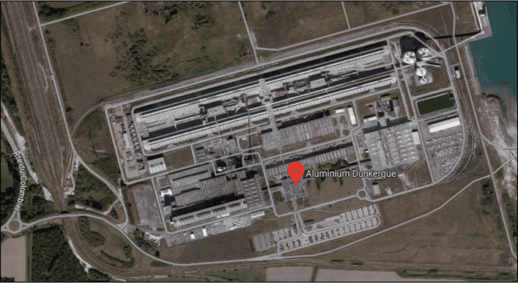
The Aluminium Dunkerque site, built in 1991, initially comprised 6 aluminum furnaces, 3 slab casting units, and 1 ingot production line. In 2004, a seventh furnace was installed, and in 2015, a second ingot production line was added. In 2022, the first ingot production line was deconstructed. The foundry hall houses furnaces lined up lengthways, with ventilators for air extraction and louvers for the introduction of fresh air.
Sizing industrial chimneys for aluminum smelting furnaces: key factors to consider
Sizing combustion chimneys
Sizing an industrial chimney for aluminum smelting furnaces depends on a number of factors, including :
- Gas flow: The gas flow generated by melting furnaces must be calculated according to their melting capacity and the type of fuel used. This gas flow rate will determine the size of the chimney needed for efficient evacuation.
- Operating temperature : Aluminum smelting furnaces generally operate at high temperatures. It is important to ensure that the chimney is sized to withstand these temperatures without deforming or deteriorating.
- Fume composition: The fumes produced during aluminum smelting may contain harmful compounds such as aluminum particles, toxic gas emissions or products of incomplete combustion. It is important to size the chimney according to the composition of the fumes, to ensure adequate evacuation and prevent any harmful impact on the environment.
The height of the chimney is determined by pollutant emission levels and the presence of obstacles that could impede gas dispersion. It may not be less than 10 metres. This measurement is established in accordance with articles 53 to 56 of the decree of February 2, 1998, or calculated on the basis of the results of a study of gas dispersion conditions adapted to the site.
On-site audit
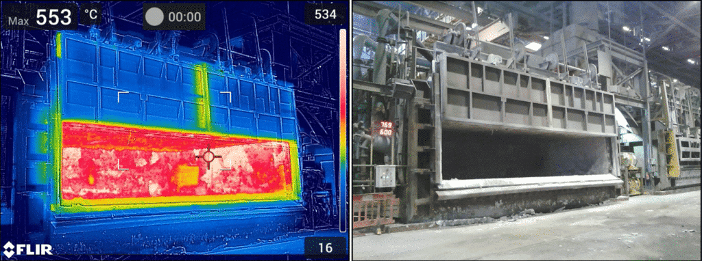
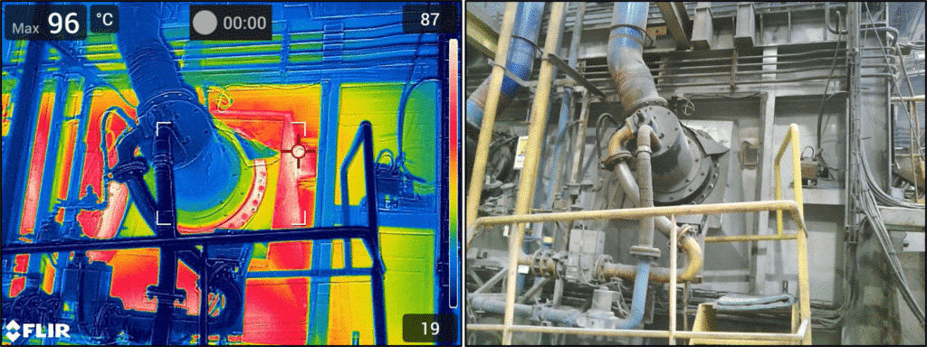
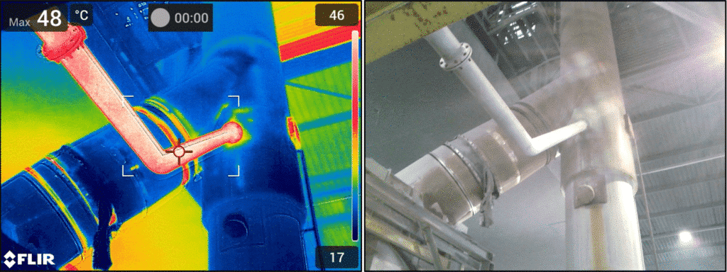
Thermal camera
CFD is used to simulate and analyze the behavior of fluids, such as air, water, gases, etc., inside a furnace, in order to understand heat transfer, flow velocity and mixing phenomena. Thermography, on the other hand, visualizes temperature variations using infrared cameras, which convert temperature differences into thermal images. These images provide invaluable information on hot and cold zones and temperature differences within the industrial furnace.
Bringing technology to the furnace industry: using CFD and thermography to better understand and control thermal processes in industrial furnaces.
Through the combined use of thermography and CFD, engineers can take corrective action to improve furnace energy efficiency, optimize production processes,reduce operating costs and maximize overall performance. The benefits of thermography in CFD simulations for industrial furnaces are manifold. It provides real-time, non-invasive and non-disruptive data on temperatures inside the furnace, making it easier to detect potential problems, such as excessive hot spots or areas of insufficient cooling.
In addition, industrial thermography provides a clear and comprehensible visualization of temperature gradients, helping to make sound decisions on process optimization. The aim of a thermal audit is to identify where heat is concentrated, and to create a map of hot and cold zones. It is important to note that the temperatures provided are intended to give a general estimate rather than a precise measurement.
In summary, integrating thermography into CFD simulations for industrial furnaces considerably improves understanding of heat transfer phenomena, and guides engineers towards more efficient and accurate optimization measures. This leads to improved performance, greater energy efficiency and lower operating costs for companies.
Smoke tests
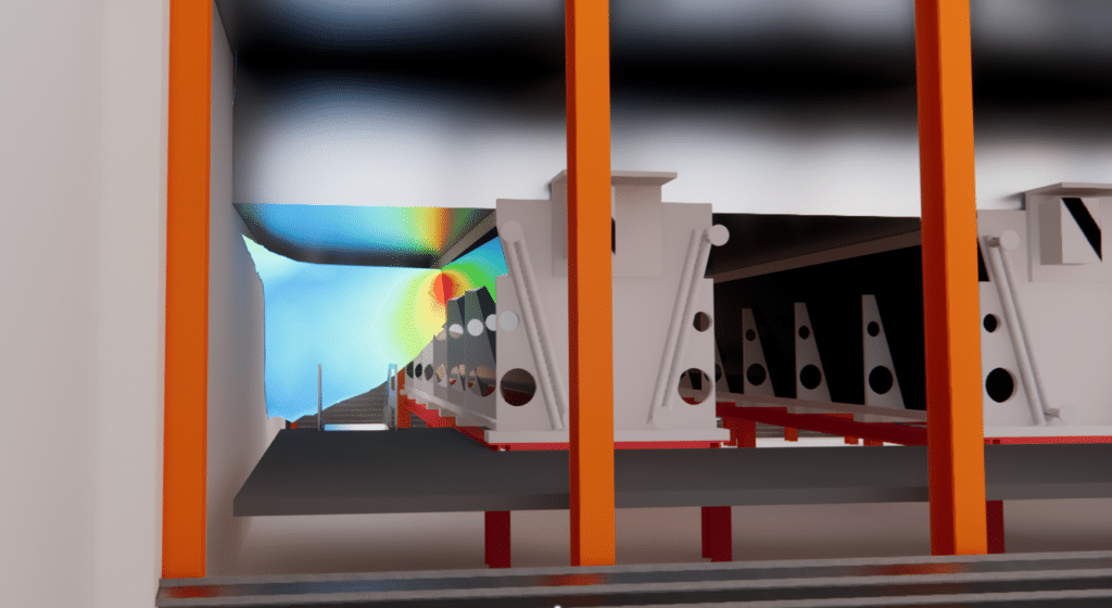
Smoke tests are designed to visualize ventilation around Furnace 7. These tests, like the thermal images, provide additional data for validating the simulations. Given the presence of openings such as the air intake and the side openings of the furnace, it is essential to consider the volume surrounding the furnace and the prevailing aeraulic conditions.
Principle of furnace operation
Furnace operation is divided into several distinct phases, including melting, holding, temperature rise, door opening and other operations. Gas flow varies during these phases, and is influenced by the number of furnaces in operation. The addition of furnace 8 in alternation is envisaged to achieve the gas flow rates required by regulations.
CFD simulation
CFD simulation for industrial chimney and duct sizing
One of the essential methods we use in our approach isCFD simulation (Computational Fluid Dynamics) or Computational Fluid Dynamics. This state-of-the-art technique enables us to analyze and model the behavior of fluids, such as gases, liquids or suspensions, using complex mathematical equations solved by computer. As a result, we are able to provide accurate, detailed predictions of aerothermal phenomena, fluid flows, heat transfer and pressure losses.
In the specific case of industrial furnace chimney design, CFD simulation is particularly useful for understanding and optimizing the combustion process. By studying the properties of the fluid (e.g. temperature, velocity, pressure) and its interaction with the various components of the chimney, we can evaluate the pressure drops, i.e. the pressures lost as the fluid flows through the system.
In addition, CFD simulation enables us to analyze the pressure rise due to natural thermal draught in the chimney. This phenomenon is essential to ensure efficient extraction of smoke and flue gases, simply by making use of the temperature difference between the inside and outside of the chimney. Thanks to our advanced modeling, we can optimize chimney design to ensure maximum thermal draft while minimizing pressure losses.
Finally, we are also studying dust erosion in flue gases, a major issue in industrial applications where abrasive materials can damage chimney walls. Using CFD simulation, we are able to predict areas susceptible to erosion, identify wear mechanisms and propose suitable protection solutions, such as the use of resistant coatings or modifications to the chimney geometry.
At EOLIOS, our personalized approach and advanced CFD simulation skills guarantee you accurate and reliable results for industrial furnace stack sizing. Contact us today to discuss your specific requirements and find out how we can help you optimize your industrial processes.
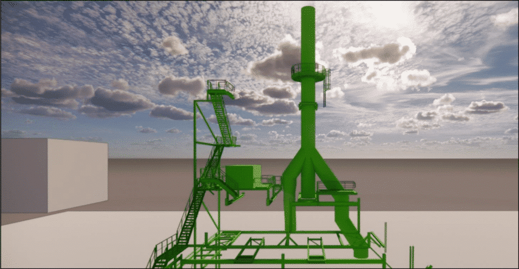
3D Model
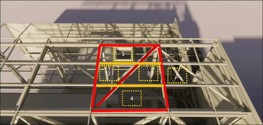
The roof structure must be locally reinforced to allow the chimney to pass through. A special reinforcement, in the form of a diagonal beam, is provided to facilitate this passage. Given the space constraints on the roof, there are five possible options for the location of this passage. Positions 1 and 5 are preferred for their accessibility and convenience.
Duct sizing
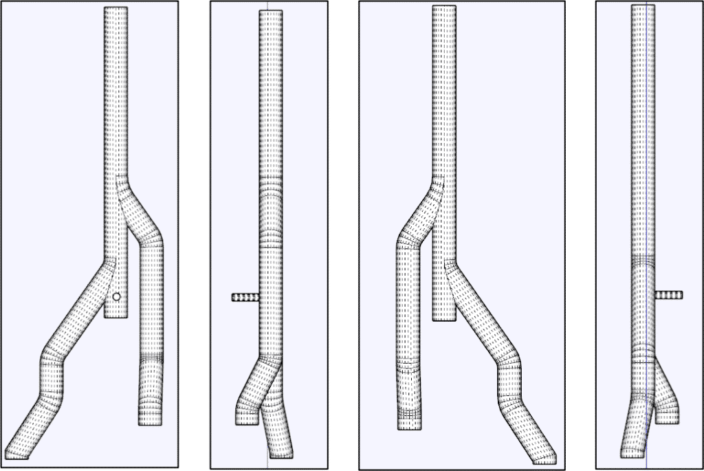
We have optimized bends and connections to improve flow efficiency. Our approach is to limit each bend to a maximum of 3 elements to control installation costs.
CFD simulation results
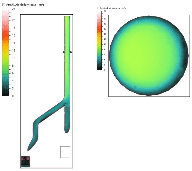
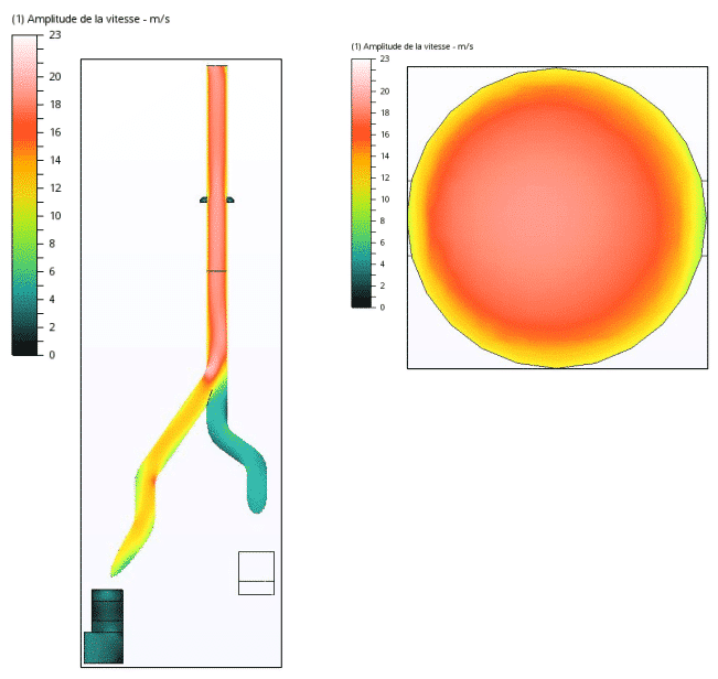
We carried out simulations for the two most demanding scenarios, i.e. the melting mode of furnaces 7 and 8, and the holding mode of furnaces 7 and 8. The main objective of these simulations was to evaluate ejection velocities and air flows at the air inlets located above the measurement point.
Performance evaluation of air inlets for melting and maintenance of furnaces 7 and 8: simulations and detailed analyses
We carried out simulations for the two most demanding scenarios, i.e. the melting mode of furnaces 7 and 8, and the holding mode of furnaces 7 and 8. The main objective of these simulations was to evaluate ejection velocities and air flows at the air inlets located above the measurement point. Simulations were carried out to assess the performance of the air inlets above the measuring point in two scenarios: melting of furnaces 7 and 8, and maintenance of furnaces 7 and 8. The dimensions of the air inlets were similar to those of the stacks for furnaces 1 to 6. For the first stack, simulations showed that the air inlets had a limited impact on the flow, with inflows well below the set target. Nonetheless, stack exit velocities remained within target. In the case of the second stack, head losses caused by steep bends in the shaft of furnace 8 had a negative impact on the draught. This reduced the supply of outside air, and in the case of melting furnaces 7-8, reversed the direction of flow. However, the difference in temperature distribution between the two stacks remained minimal.
Continue on this topic
Video summary of the study
Discover other projects
Simulation of saturated vapour capture on a continuous casting line
Simulation of saturated vapour capture on a continuous casting line
Radiation and ventilation study of an industrial ingot mould
Sizing – Chimney – Laboratory
Smoke treatment system – CO2
VOC treatment process improvement
Sizing an industrial chimney – Furnace
Stratification of a thermal storage tank
Generator sets – GE1
Simulation of saturated vapour capture on a continuous casting line
Simulation of saturated vapour capture on a continuous casting line
Radiation and ventilation study of an industrial ingot mould
Study of natural ventilation – Steelworks
Air quality improvement – Plant
Sizing – Chimney – Laboratory
High-temperature process plant
Natural ventilation – Metallurgy

