Home » Industrial Process » Study of network load losses » Sizing – Chimney – Laboratory
Sizing – Chimney – Laboratory
Sizing a chimney network in the laboratory
The main aim of this study is to understand and improve the performance of flue pipes in combustion systems, with particular emphasis on reducing pressure drop and eliminating the risk of condensation. Flue pipes, if not properly designed, can create barriers in the flow, increasing the need for additional power to maintain the required flow, resulting in significant energy inefficiency. This is a crucial issue, as it affects not onlyoperational efficiency but also the overall sustainability of systems.
In addition, thebuild-up of condensation inside pipes can lead to corrosion problems, shortening the service life of the infrastructure. This calls forin-depth study of the thermal and dynamic behavior of fluids within pipes, in order to propose appropriate design solutions that minimize these undesirable effects. Ultimately, the project aims to promote the safety and sustainability of smoke management systems.
Design and calculation of pressure drops in laboratory flue pipes
Year
2025
Customer
French national metrology and testing laboratory (LNE)
Location
France
Typology
Porcess Industriel
Continue navigation :
Our other projects :
Latest news :
Technical file :
Our expertise:
Reducing pressure drop and condensation in combustion systems
Diagnosis of flue constraints for optimum performance
Flue pipes are subject to a number of technical and operational constraints that must be taken into account to ensure optimal operation. Pressure losses are a major concern, as they represent the resistance that smoke must overcome to be evacuated from the system, often requiring additional energy. These losses can be caused by structural elements such as excessively tight elbows, abrupt constrictions or internal devices such as baffles, which disrupt the laminar flow of fumes. Another critical constraint is the management of condensation inside the pipes.
When temperatures fall below the flue gas dew point, condensation can occur, leading to a build-up of potentially corrosive liquid. This not only damages the pipes, but can also compromise the safety of the entire system. Industry and regulatory standards also impose strict safety and sustainable performance requirements to prevent these risks. Finally, practical constraints such aslimited space for pipe installation,access for maintenance and compliance with local regulations can have a considerable influence on system design and installation.
Technical criteria for maximizing flue pipe efficiency
To ensure theefficiency and reliability of flue pipes, a number of technical and design criteria must be strictly adhered to. First of all, reducing head losses requires a design that favors the smoothest, most constant smoke flow possible, minimizing bend angles and avoiding obstacles in the flow path. This structural optimization limits the need for additional energy to move the flue gases, thereby reducing energy costs.
In addition, adequate thermal insulation is essential to keep internal pipe temperatures above the calculated dew points for the various flue gas components. This helps prevent any condensation that could not only damage the pipes, but also lead to leaks and unexpected damage. The choice of materials is also crucial, requiring corrosion-resistant metals or coatings designed to withstand the acidic conditions potentially caused by fumes.
CFD modeling: a revolution in flue gas analysis
Improving flue gas performance with CFD technology
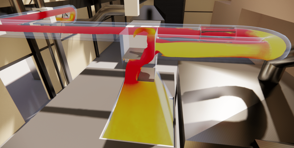
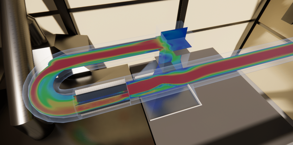
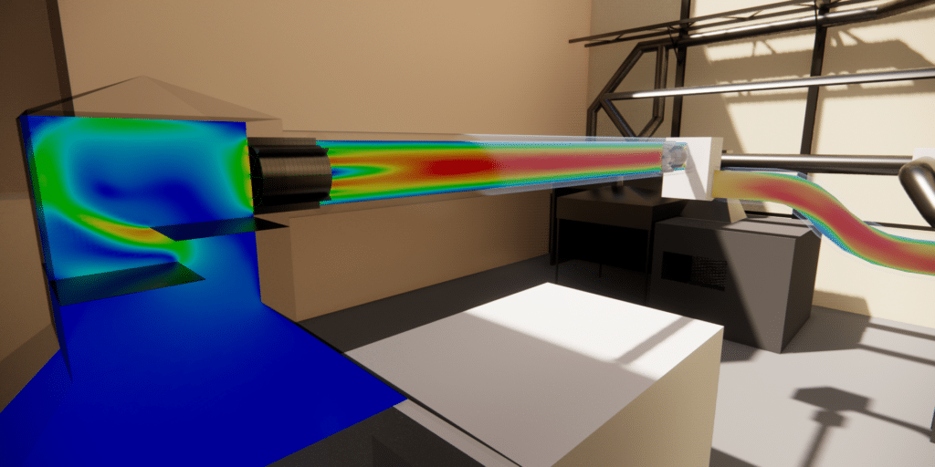
Computational fluid dynamics (CFD) modeling is proving to be an indispensable tool for this study, providing analytical solutions to the complex challenges posed by smoke management. CFD offers the possibility of accurately recreating the internal conditions of smoke ducts, enabling detailed visualization of fluid flows. Thanks to this technology, it is possible to assess the impact of each design element on load losses, optimize configurations to limit these losses, and thus improve theoverall energy efficiency of the system. Simulations can also predict temperature variations along the pipe walls, identifying critical areas where the risk of condensation is highest and enabling interventions to be tested without the costs associated with manufacturing and installing a physical prototype.
By providing valuable data on the dynamic behavior of fluids, CFD makes it possible to explore different design scenarios before they are implemented, considerably reducing the time and costs associated with developing new installations. In addition, the ability to model pipe performance under different operating conditions enables potential failures to be predicted and mitigated before they occur, thus contributing to system reliability and safety.
Pipe routing optimization strategies for enhanced energy efficiency
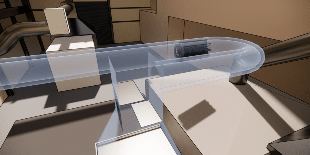
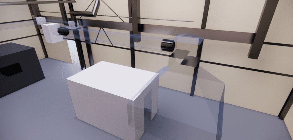
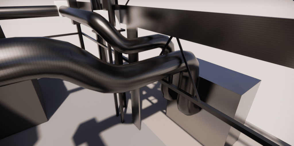
When designing the pipes, particular attention was paid to the choice of route to minimize pressure losses. Optimizing the route required careful analysis of possible configurations, taking into account spatial constraints and the inherent characteristics of the installation sites. Bends have been kept to a minimum, with a preference for gentle three-segment bends rather than sharp angles, to reduce turbulence that increases flow resistance. The pipe sections have been designed to maintain a uniform diameter, avoiding abrupt constrictions that could create bottlenecks. In addition, the coherent layout of the pipe segments has optimized the overall routing, reducing the overall length of the conduits and lowering the head losses associated with internal friction.
By integrating a CFD modeling approach into the design process, simulations were able toidentify the most efficient configurations, ensuring laminar and continuous flow while minimizing theenergy required to evacuate the fumes. Thanks to these design strategies, the proposed system not only complies with regulatory requirements but also improves overall energy performance, ensuring greater plant sustainability and efficiency.
EOLIOS optimizes flue gas in piping systems
EOLIOS is recognized for its advanced technical expertise and its ability to carry out flue gas engineering projects with rigor. With a wealth of experience in CFD modeling, EOLIOS uses the latest technologies to analyze and optimize smoke flows, ensuring that flues are both efficient and comply with the most demanding standards. EOLIOS engineers and specialists have an in-depth understanding of fluid dynamics and thermal constraints, enabling them to propose innovative, customized solutions that incorporate industry best practices.
> Read more :
Continue on this topic
Video summary of the study
Video summary of the study
Discover other projects
Study of aeraulic comfort – Middle school
Wind comfort study – Rooftop
Wind impacts on high-rise buildings: Tours Olympiades in Paris
Comfort – Rooftop of a palace – Casablanca
Tour Liberté – La Défense
Impact of wind on a solar power plant
Cooling towers – ICPE
Pedestrian comfort study – La Défense
Confort au Vent – PSG training center
Wind study – La Défense
Fine particle capture in a metro station
Sharaan by Jean Nouvel resort
Air coolers – Critical study – Heat wave
Fine dust measurements
Balenciaga – Wind potential


