Home » Smoke treatment system – CO2
Smoke treatment system – CO2
In a few words
EOLIOS ingénierie provided its expertise to improve a plant’s gas redirection network.
Smoke treatment system - CO2
Year
2024
Customer
NC
Location
France
Typology
Industrial Process
Continue navigation :
Our other projects :
Latest news :
Technical file :
Infrastructure reconfiguration project: development of a CO2-based smoke treatment system
New pipeline network for CO2 capture: optimizing furnace emissions
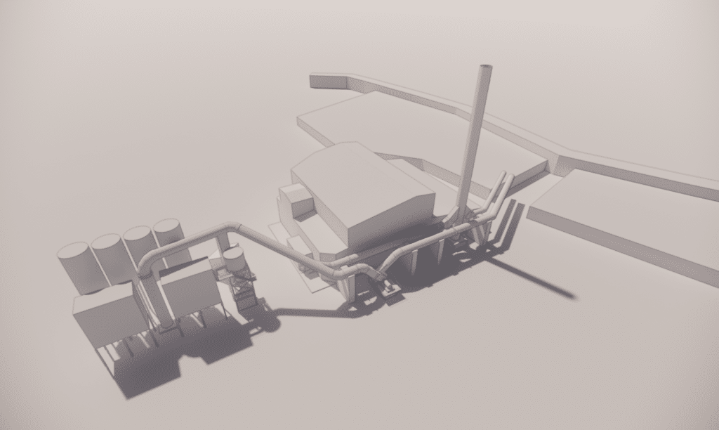
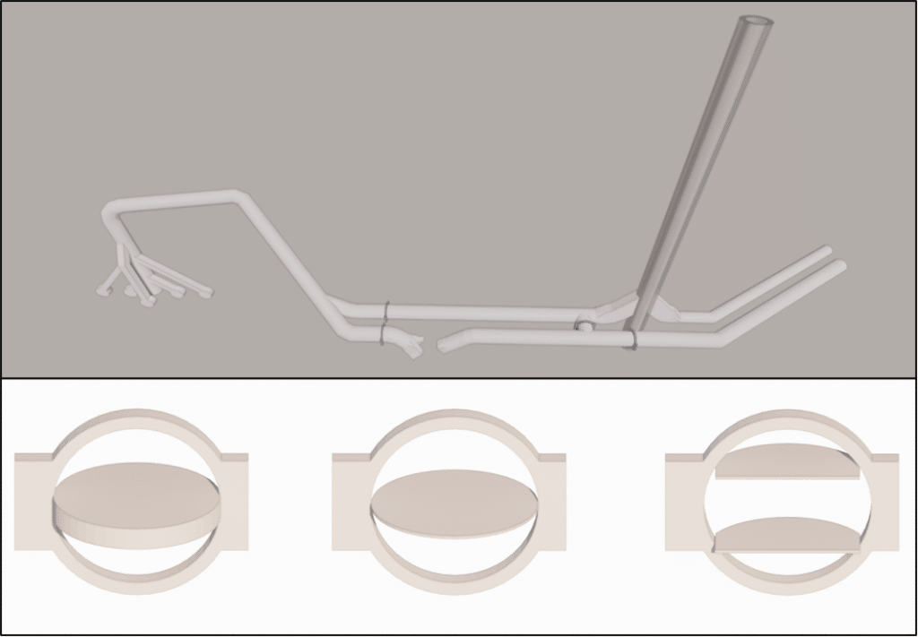
As part of the development of a smoke treatment system, with a particular focus on carbon dioxide (CO2) treatment, the project aims to reconfigure the existing infrastructure. This involves setting up a new network to channel emissions from the furnaces to the CO2 capture system.
The system consists mainly of an in-line fan, four dampers for insulation and regulation, and a double-flow chimney with concentric ducts. The aim of this document is to present the results obtained from simulations carried out for the three operating modes studied.
Potential problems for smoke extraction: in-depth analysis
In our study, we focus on several key aspects. First of all, we’re taking a close look at the problems that could affect gas extraction.
Another important aspect of our study is the identification of areas at risk of acid condensation. Acid condensation can lead to excessive corrosion of pipes and equipment, resulting in major damage and high repair costs. By analyzing the temperature and humidity conditions in the system, we are able to identify areas at risk and propose recommendations to minimize the effects of corrosion.
Finally, our study also includes an assessment of pressure losses in the ducts. Head losses are decreases in fluid pressure that occur as the fluid flows through the pipes. These load losses can have an impact on overall system efficiency, and can lead to higher energy costs or even system inefficiency. By analyzing the network design and using advanced mathematical models, we are able to estimate these load losses and propose solutions to reduce them.
3D model and contextual elements for CFD simulation
Potential problems for smoke extraction: in-depth analysis
The initial design of the 3D model is based on the documents received. Due to certain software limitations, the geometric representation of the registers is simplified, focusing exclusively on the pivoting blades.
Outdoor conditions
Several external conditions had to be considered:
- Conditions for studying condensation zones
- Conditions for thermal draft analysis
We examine three operating modes:
- basic mode (mode 1),
- a variant of the basic mode (1.1 x mode 1+),
- mode 1+ full bypass.
In basic mode, the flow is directed to the CCU with specific registers closed. The 1.1 x Mode 1+ variant directs part of the flow to the chimney while maintaining a connection to the CCU, while Mode 1+ full bypass directs the entire flow to the chimney with appropriate damper adjustments.
CFD simulation: Initial and improved configurations of the smoke treatment network
Results with initial configuration
The following section presents the simulation results, highlighting various aspects such as pressure, velocity and temperature.
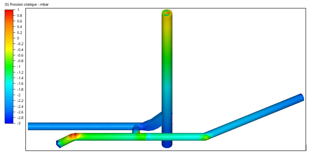
Pressure losses are evaluated by calculating the average pressure difference between the model’s inlet and outlet cross-sections, providing essential information for future improvements.
Two situations were examined: the efficiency of gas extraction under unfavorable draught conditions (35°C, 1m/s) and the possible risk of condensation and acid condensation under favorable conditions ( -10°C, 14.3 m/s).
Studying the challenges of gas extraction: identifying dead zones, managing condensation and dealing with pressure loss
Pressure decreases slightly from upstream to the chimney outlet. Nevertheless, a significant pressure drop occurs at a damper due to its limited opening. The increase in pressure at the chimney outlet is due to the presence of a bidirectional flow, disrupting the extraction of gases and leading to a rise in pressure.
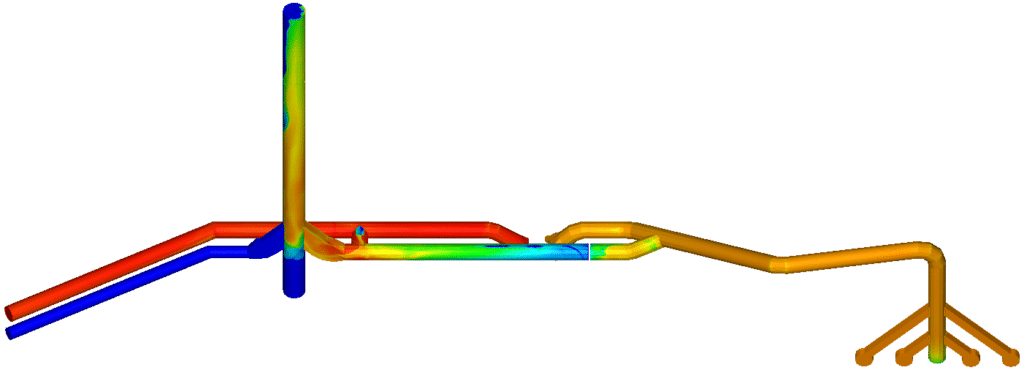
The dead zone reaches a minimum temperature, while the drop in temperature towards the top of the chimney indicates that air is entering part of the chimney.
The aim of the study was to identify potential problems affecting gas extraction and the possibility of acid condensation, while assessing pressure drops. Two scenarios were examined: gas extraction efficiency under unfavorable draught conditions, and the risk of condensation under favorable conditions.
The results highlight three major issues:
- A notable inactive zone in the first bypass in full bypass mode,
- An extended inactive zone when a specific control is opened, encouraging condensation and leading to pressure losses,
- An area where condensation appears in the chimney with a double flow.
Despite these challenges, we have sized the duct insulation, which appears to perform well overall, with only slight thermal losses. Inactive areas with possible defects could be specifically treated.
Results with enhanced configuration
Results with improved confiuration
This section summarizes simulations of geometric modifications, including setting the Y of the first bypass, adding an isolation damper, and reducing the height of the central chimney. Extreme conditions were used to assess pressure losses and acid condensation in the pipes.
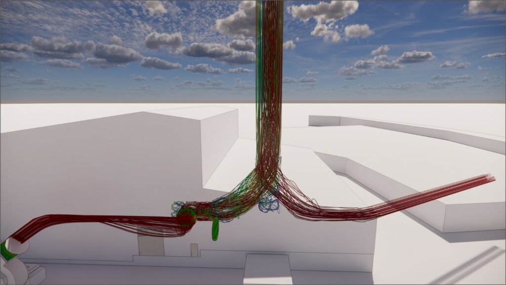
The pressure distribution shows a marked similarity with the basic geometric configuration. This is explained by the persistence of a bidirectional flow at the chimney outlet, albeit of lesser importance.

The figure above shows that a bidirectional flow persists in the upper part of the chimney.
The illustration shows how speed is distributed upstream of the fan. This distribution is not a problem, as the reduced cross-section at the isolation damper prevents the creation of an inactive zone at low speed, and instead generates a zone at high speed.
The aim of this section was to evaluate three specific optimizations: adjusting the Y of the first bypass, adding an insulation damper near the second bypass, and reducing the height of the central chimney.
The first optimization involved modifying the Y of the first bypass to improve flow and reduce dead zones. Simulations showed the disappearance of low-temperature zones and a reduction in head losses.
The second optimization added an isolation damper near the second bypass, eliminating a large dead zone.
The third optimization reduced the height of the central chimney, showing a significant improvement, especially in the worst-case scenario.
CFD studies: understanding and optimizing fluid dynamics in industrial stacks
Understanding the fluid dynamics of industrial chimneys is essential to ensure their optimal operation. As experts in CFD (Computational Fluid Dynamics) simulation, we specialize in carrying out these crucial studies.
Our know-how enables us to carry out various analyses for industrial chimneys, including :
- Thermal draft assessment
- Pressure loss analysis
- Managing erosion caused by dust in flue gases
- Atmospheric dispersion analysis in compliance with air quality standards
- Assessing structural stability in the face of external costs
- Dew point analysis to prevent condensation and its harmful consequences.
Continue on this topic
Video summary of the study
The project aims to reconfigure the existing infrastructure to develop a smoke treatment system focused on reducing carbon dioxide (CO2) emissions.
This requires the implementation of a new pipeline network to capture and direct furnace emissions to the CO2 capture device.
The network consists of a online fan and dampers for insulation and regulation as well as a double-flow chimney with concentric ducts.
The study focuses on several important aspects.
Firstly, it examines the problems likely to affect gas extraction These include areas at risk of acid condensation, which can lead to excessive corrosion of pipes and equipment.
By analyzing temperature and humidity Recommendations are made to minimize the effects of corrosion.
The study also includes an assessment of pressure losses in ducts, which can affect overall system efficiency and lead to higher energy costs.
Advanced mathematical models are used to estimate these pressure losses and propose solutions to reduce them.
The simulations carried out for the different operating modes show a significant significant pressure drop across the dampers a bi-directional flow disturbing gas extraction and inactive zones favoring condensation .
Cependant, des geometric improvements such as adjusting the Y of the first bypass, adding an insulation damper and reducing the height of the chimney have reduced these problems.
In conclusion, the infrastructure reconfiguration project to develop a CO2-based smoke treatment system requires geometric adjustments and optimizations to improve gas extraction, reduce pressure drops and minimize condensation risks.

