Securing a commercial site – CFD study of wind risk
Securing a commercial site - CFD study of wind risk
Year
2025
Customer
Leroy Merlin
Location
France
Typology
Air & Wind


Home » Air & Wind » Numerical simulation of pedestrian comfort in an urban environment » Securing a commercial site – CFD study of wind risk
EOLIOS ingénierie's mission: CFD simulation and wind control expertise for logistics and commercial sites
EOLIOS engineers are experts at analyzing air flows on wind-exposed outdoor sites.
EOLIOS ‘ expertise in CFD(Computational Fluid Dynamics) simulation and the analysis of external aeraulic phenomena enables us to support operators in understanding and controlling the effects of wind on their sites. In storage, loading, circulation or outdoor work areas, our know-how enables us to identify sensitive areas, understandacceleration, channelling orengulfment mechanisms, and propose concrete solutions to improve comfort, safety and continuity of operation.
EOLIOS is a leading player in CFD simulation applied to outdoor environments. Our studies are based on field audits, real-life surveys, precise 3D modeling and simulations, enabling us to design targeted solutions tailored to the real constraints of each site.
When wind becomes more than a nuisance
A methodological approach to understanding wind effects
The three studies carried out concern Leroy Merlin stores in the south-west and south of France, on sites where wind is a real operating constraint. Although the configurations are different, the three cases have one thing in common: wind does not act uniformly across the entire site, but concentrates in certain sensitive areas, where it disrupts usage, operations and working conditions.
Theaim is not simply to note that the wind is present, but to understand how it interacts with a building, its accesses, its storage volumes, its open spaces and its immediate environment. This common approach makes it possible to construct a transversal reading, while taking into account the particularities of each site. To achieve this, the study is based on a structured approach, carried out in the following stages:
- On-site audit, to observe phenomena in real-life conditions, understand operating constraints and identify feasible solutions.
- Meteorological study of the site, with records of prevailing wind directions, average wind speeds and maximum wind speeds felt at the nearest weather stations.
- Definition of a Eurocode wind at domain entry, based on a velocity model that varies according to the base velocity measured at a weather station,altitude, apparent terrain roughness andorography.
- CFD study to determine air velocities, pressures and significant aeraulic phenomena.
- Formulation of concrete technical recommendations aimed at limiting the impact of wind, with support for the design of selected solutions, supplemented if necessary by additional CFD simulations to assess their effectiveness.
Measuring the stakes for the operation
On large-scale or light logistics sites, wind can become much more than a simple discomfort when it concentrates on work, traffic, loading or storage areas. Above certain thresholds, it disrupts activities, hinders movement, stirs up dust and light objects, and can lead to the displacement or breakage of exposed equipment. Its consequences directly affect user safety, theorganization of operations and business continuity.
Depending on site configuration, these phenomena can take various forms: acceleration at an opening, recurrent exposure of outdoor areas, sweeping of service yards or air circulation between several spaces. So thechallenge is not just to qualify a nuisance, but to understand how wind actually affects the operation of the site and its ability to evolve in the long term.d’erreurs humaines. This automation includes server management, energy consumption monitoring and preventive maintenance.
Working conditions and air comfort
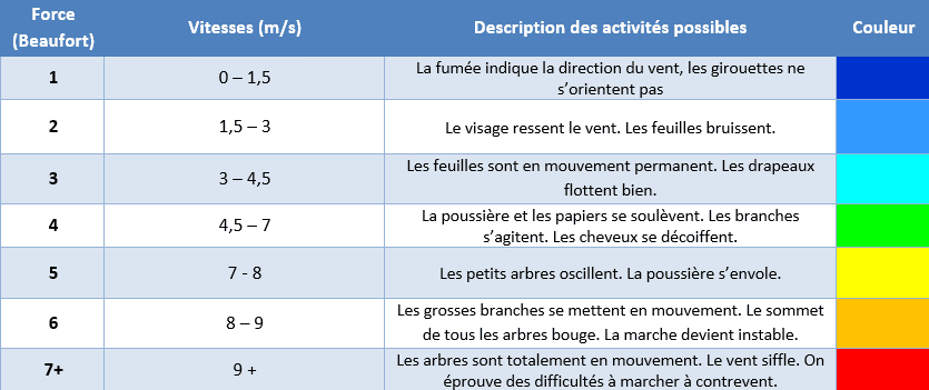
Wind comfort is a central issue in this study. As soon as wind speeds become sufficiently high to interfere with movements, disrupt certain operations or destabilize people, wind becomes an operating constraint in its own right. As the table below illustrates, certain uses can be disrupted at 4.5 m/s and above, while walking stability can be affected above 8 m/s. These benchmarks provide a simple link betweenwind intensity and its practical effects on users, work areas and infrastructures.
Particularly exposed storage areas
During the audits, storage areas were found to be particularly sensitive to the effects of wind. Whether material yards, rear areas, new outdoor storage zones or areas close to logistics access points, these spaces often combine several unfavorable factors: exposure to prevailing winds, unobstructed upstream environment, channelling effects between built volumes and air circulation accentuated byopen doors.
These configurations can generate high air velocities, penalizing handling and loading operations, while increasing the risk of stored objects moving, falling or breaking. Thechallenge is therefore to better control exposure to the wind in these sectors, in order to secure their use andsupport the planned changes in logistics.
Defining a reference wind with the Eurocode
Before analysing the effects of wind on a site in detail, it is necessary to define a common frame of reference. This is the role ofEurocode 1 – Wind actions, which provides a normative basis for characterizing the wind to be taken into account in thestudy.
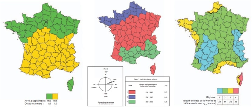
A base speed derived from regulatory zoning
The base speed Vb,0 corresponds to an extreme but rare wind event, associated with a mean return period of around 50 years. It is defined as a speed measured over 10 minutes at 10 meters above ground level, in a rural area. This value depends directly on the geographical location of the project, and is determined on the basis ofEurocode zoning.
A reference speed adapted to the project context
The base speed can then be adjusted to better represent the actual project context. Two correction coefficients are used to define the reference speed Vb.
- The Cdir direction coefficient takes into account the fact that the strongest winds do not necessarily blow in the most unfavorable direction for the site. It can therefore be used toadapt the reference speed when certain critical directions are unlikely.
- The Cseason coefficient reflects the fact that extreme winds do not occur with the same intensity or frequency throughout theyear. For permanent structures, this coefficient is generally taken to be equal to 1. For temporary installations, however, it can be reduced.
The Eurocode base speed Vb is then calculated using the following formula:

Take into account the influence of relief
Relief can locally modify wind speed. Hills, ridges and escarpments can accentuate flows and generate local accelerations. TheEurocode incorporates this effect through the orographic coefficient Co(z).
When the average slope of the terrain to the wind is less than 3°, the effects of orography can be neglected. In this case, the coefficient is set equal to 1.
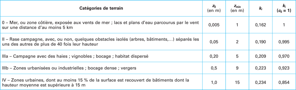
Terrain roughness, an essential parameter
Wind does not evolve in the same way over open ground, vegetated areas or urban environments. To take account of this effect, theEurocode introduces the roughness coefficient Cr(z), which describes the variation in wind speed withaltitude.
It is obtained as a function of Z0, Zmin, Zmax and Kr (obtained according to the category of land) by the following formula:

With Z0 the roughness length of the terrain category considered, Zmin the lower limit of validity of thelogarithmic aspect of the roughness coefficient, Zmax the maximum height of the study area and Kr the terrain factor.
Terrain roughness, an essential parameter
From the reference speed, roughness andorography, it is possible to calculate the average wind speed as a function ofaltitude.

This relationship produces a logarithmic velocity profile, much more realistic than a uniform velocity applied to the entire height of the domain. This profile is an essential step in the preparation of simulations, as it describes how the wind is structured beforeinteracting with the buildings and their environment.
This first approach allows us to characterize the average behavior of the wind, but is not sufficient on its own to account for its most intense variations. Beyond the average wind, it is often necessary to take into account gusty winds, which incorporate theturbulent intensity and temporal variability of the wind. These gusts represent a more severe level of stress, useful for completingflow analysis.
The gust velocity profile can be determined from the following relationship:

Where Z represents the height, Z0 the roughness height of the terrain category in question, and Kl the turbulence coefficient of the terrain category in question.
Theadvantage of this approach is that it doesn’t inject an arbitrary speed into the model, but a wind constructed from a recognized reference frame, then adjusted to the actual site context. TheEurocode thus provides the starting structure: CFD simulation then takes over to show how this wind deforms,accelerates, channels or concentrates on contact with the project geometry.
Site modeling and simulation
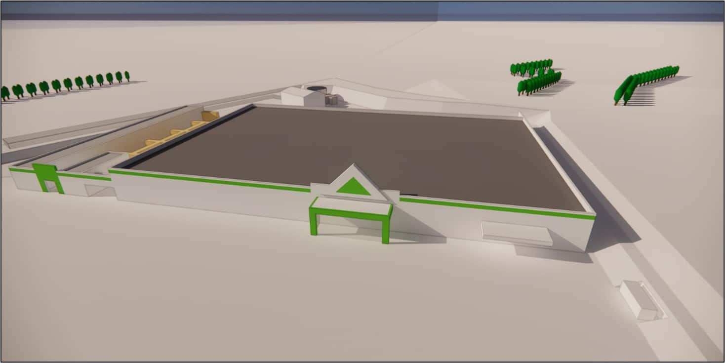
The modeling process used to analyze wind behavior on the sites. It is based firstly on the construction of a 3D model representative of the project and its immediate environment, and then on an aeraulic simulation to study how air flows interact with buildings, openings and outdoor spaces. This approach provides an essential basis for understanding the phenomena observed and guiding design choices.
A model based on the project and field observations
Modelling is not based on a single source of information. It is based on a number of complementary elements: available documents on the project, transmitted plans, on-site observations, photographic surveys, aerial views and geographical landmarks available on the site and its surroundings.
This crossover approach is important, as it brings the numerical model closer to the real situation. Field observations play a special role here: they enable us to verify certain volumes, confirm the position of openings, understand the organization of uses andidentify the elements that really influence air movements.
Integrating the site into its surroundings
Wind does not only depend on the volume under study, but also on itssurroundings. This is why the model also includes the area surrounding the site, with a perimeter sufficiently wide to take account of masking, channelling or deflection effects linked to thesurrounding environment. This broader reading is essential to understanding the phenomena observed locally.
Study wind behavior using CFD simulation
CFD, or Computational Fluid Dynamics, is used to simulate air flows around a site, and to reproduce the main aeraulic phenomena. In the context of this study, it offers a detailed reading of how wind interacts with buildings, openings, nearby obstacles and outdoor spaces.
Based on a 3D model of the site, the calculation is performed on a mesh composed of a large number of cells, with particular refinement in the most sensitive areas to better represent local flow variations.
The simulation is based on the numerical resolution of the physical laws governing air movement, supplemented by a turbulence model adapted to the complex geometries encountered on this type of project. This approach makes it possible to identify zones of acceleration, channelling or recirculation of the wind, and is thus a valuable tool for understanding the phenomena observed in the field and comparing different development hypotheses. Finally, the quality of the results is verified by checking the convergence of the calculation, to guarantee a reliable and usable basis for analysis for the project.
Site modeling and simulation
The results show how the wind is structured at each site, and why certain configurations are particularly detrimental to operations. It reveals the most sensitive sectors, while highlighting the mechanisms that shape flows around buildings.
This stage provides an essential basis for comparing the scenarios studied, guiding development choices and helping to define responses that are truly adapted to the site’s constraints, uses and operating conditions.
Analysis of current phenomena
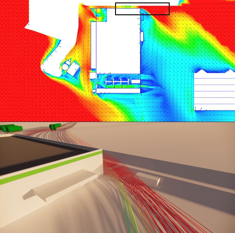
After reading the simulations, the same observation can be made for all three stores: disorders are caused not only by theexposure of the site, but also by the way in which the building, openings, angles, circulation and the surrounding relief organize run-off.
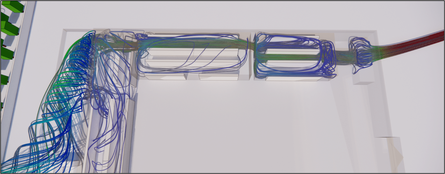
The simulations reveal channelling,local acceleration,engulfment and bypass effects, which concentrate stress on a few key sectors of the operation. Loading and storage areas appear to be the most vulnerable, as they combine through-flow, corner exits and narrow passages.
In several cases, internal or semi-internal draughts are also highlighted, directly linked to theorganization of accesses and theopening of certain doors. This reading allows us to go beyond the simple observation of discomfort, andidentify precisely the mechanisms at play. Above all, it shows that an effective response is not to treat the entire site uniformly, but to intervene where the geometry amplifies the phenomena and weakenseveryday use.
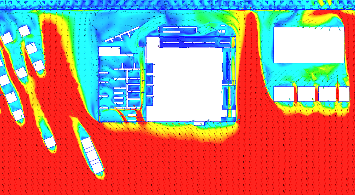
This principle was very clearly demonstrated in Perpignan, where the loading zone exhibited particularly marked local acceleration. As it traveled along the north side of the building, theflow would narrow and then abruptly exit this area, generating a sudden blast effect likely to destabilize customers and cause property damage. This case is a good illustration of how a building configuration can transform general exposure into a very real nuisance.
Compare simulation with reality
Before making any recommendations, EOLIOS checked the simulation against the reality on site, usinganemometer readings taken by our teams. This measurement phase enabled us to check that the most exposed areas identified by the CFD corresponded to the sectors where the effects would actually be felt duringoperation. Modeling the initial configuration not only illustrated the flows, but also confirmed the findings observed on site, with the same points of concentration,acceleration and annoyance around the buildings. This consistency between measurements and simulation gives thestudy its full value, making CFD a genuine decision-making tool for designing targeted, credible solutions.
The impact of windbreaks
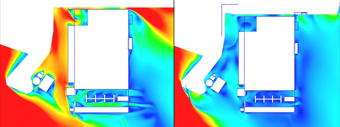
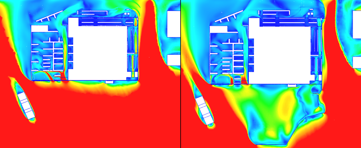
Following analysis of the initial configuration, a second design incorporating windbreaks at the most exposed locations was studied in order to assess their ability to correct the phenomena observed on site. Modeled using the same CFD approach as the existing state, this new configuration makes it possible to directly compare the to measure theconcrete contribution of these devices in the most sensitive areas.
Positioning windbreaks
Windbreaks are devices designed to slow down and homogenize air flows in exposed areas. Their function is not to totally block the wind, but to filter it in order to limit local accelerations, reduce turbulence and create more stable spaces for use. Depending on site constraints, they can take the form of technical structures with controlled porosity, or plant-based solutions such as hedges, more integrated into the landscape. Properly positioned, they provide an effective response to improve comfort and safety in the most sensitive areas.
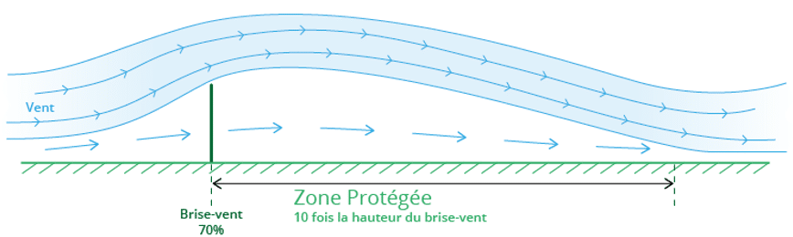
Thestudy of the three stores shows that there is no standard answer. Each site has its own specific configuration, with constraints in terms of layout, traffic flow,openings and relief that call for a specific system in terms of height, length and positioning. Some environments already havepartial natural screens, such as merlons, embankments or vegetated areas, which influence air trajectories but are not sufficient to protectall the sectors concerned. The choice of a windbreak must therefore be considered on a case-by-case basis, taking into account both theexisting environment and the uses to be preserved.
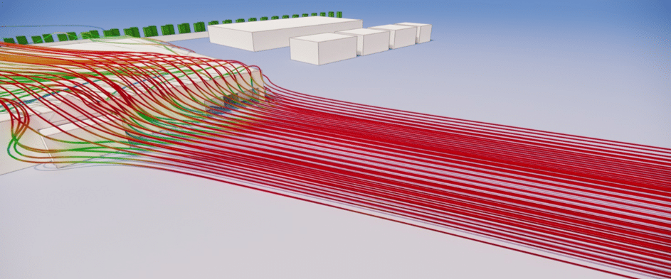
Comparison with initial design
The simulations clearly demonstrate thebenefits of windbreaks when positioned in the most exposed areas. In theinitial state, run-off was concentrated at access points, building corners, open passageways and storage areas, with direct effects on user comfort and safety. After integrating these devices, the flows are diverted, lifted or dissipated further upstream, sharply reducing local accelerations and making the areas concerned considerably more stable. This comparison highlights a concrete improvement in the functioning of outdoor and semi-open spaces, with targeted developments capable of transforming their quality over the long term.
EOLIOS: your strategic partner for customized CFD solutions to wind problems in commercial environments
EOLIOS’ expertise in CFD simulation applied to outdoor environments goes far beyond simple diagnosis. Our know-how consists in transforming complex phenomena into concrete levers for action, in the service of comfort, safety and operating performance. Each study is conceived as a tailor-made response, adapted to the configuration of the site, its uses and its real constraints. EOLIOS ‘ ability to combine detailed technical analysis, field reading and operational recommendations makes it a trusted partner for securing wind-exposed areas and supporting projects that are more robust, more comfortable and more sustainable.
Our teams are at your disposal to study your outdoor air problems, identify sensitive areas and define solutions adapted to your site.
Find out more:
Video summary of the study
Summary of the study
The study carried out by EOLIOS ingénierie analyzed the effects of wind on three Leroy Merlin stores located in particularly exposed contexts. Thanks to an approach combining on-site audits, meteorological analysis, 3D modeling and CFD(Computational Fluid Dynamics) simulations, EOLIOS was able to precisely identify sensitive areas, understand windacceleration, channelling andengulfment phenomena, and assess their consequences on comfort, safety and business continuity. In particular, the study highlighted the vulnerability of storage and loading areas, as well as outdoor spaces, to locally enhanced runoff due to site geometry and access arrangements. By comparing numerical results with field measurements, EOLIOS was able to confirm the reliability of its analysis and design targeted solutions, such as windbreaks adapted to each configuration. This approach demonstrates the value of CFD simulation as a decision-support tool for designing more robust, safer and more durable layouts in the face of external aeraulic constraints.
Video summary of the mission
Discover other Air & Vent projects
Impact of wind on a high-rise building
CFD air quality control study – Issy underground RER station construction site
Controlling wind erosion on a solar power plant
Securing a commercial site – CFD study of wind risk
Fine particle capture in a metro station
Impact of wind on a solar power plant
Study of aeraulic comfort – Middle school
Wind comfort study – Rooftop
Wind impacts on high-rise buildings: Tours Olympiades in Paris
Comfort – Rooftop of a palace – Casablanca
Tour Liberté – La Défense
Cooling towers – ICPE
Pedestrian comfort study – La Défense
Confort au Vent – PSG training center
Wind study – La Défense
Sharaan by Jean Nouvel resort
Air coolers – Critical study – Heat wave
Fine dust measurements
Balenciaga – Wind potential